
TM 11-5840-360-14-1-1
REASSEMBLY AND ALIGNMENT
1. Reinstall the Resolver Drive and NSK Exciter PCB assemblies on the NSK Assembly. Verify that all connections are
secure.
2. Perform the NSK alignment procedures detailed in the maintenance section of the basic radar manual.
3. Reinstall the stress bar and upper access cover of the Indicator and return the unit to service.
DOCUMENTATION
Annotate the schematics and Replaceable Parts Lists of the NSK Assembly (A9) and the NSK Exciter PCB (A9A2) of the
Instruction Manual to reflect the changed component values and part numbers.
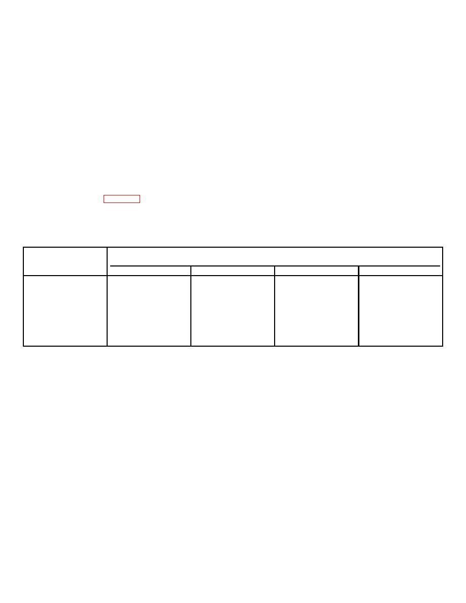
ASSEMBLY REPLACEMENT
For ordering purposes, Table A-1 lists the part numbers of the complete assemblies which are factory assembled with the
correct components for the four acceptable input voltages.
Table A-1 NSK Assemblies
Assembly
Part Number
70 Volt
50 Volt
35 Volt
28 Volt
NSK Assy (A9)
167210-1
167210-2
167210-3
167210-4
Resolver Drive
167188-1
167188-2
167188-2
167188-2
Assy (A9A1)
NSK Exciter
169456-1
169456-2
169456-3
169456-4
Assy (A9A2)
A-19


 Previous Page
