Home
Download PDF
Order CD-ROM
Order in Print
Home
>
Radar Maintenance and Parts Manuals
>
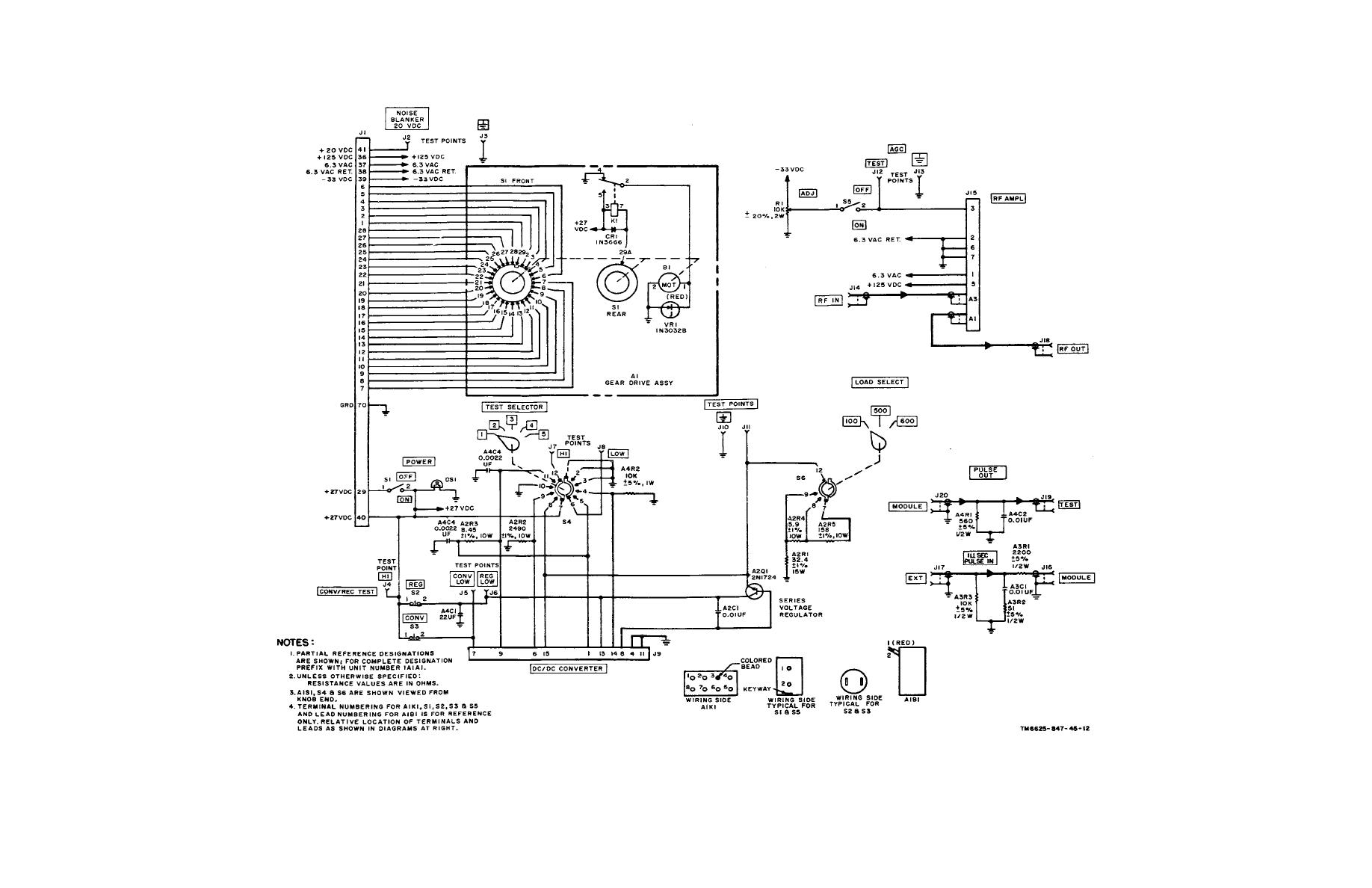
> Figure 6-7. Common module tray A1A1, schematic diagram.
Figure 6-6. Test set IF oscillators A1A2, A1A3, and A1A4, schematic diagram.
Figure 6-8. Common module tray A1A2, schematic diagram.
TM-11-6625-847-45 Simulator Radio Frequency SM-442A/GRC Manual
Page Navigation
107
108
109
110
111
112
113
114
115
116
117
TM
11-6625-847-45
Figure
6-7.
Common
module
tray
A1A1,
schematic
diagram.
Change
1
6-13


 Previous Page
