Home
Download PDF
Order CD-ROM
Order in Print
Home
>
Radar Maintenance and Parts Manuals
>
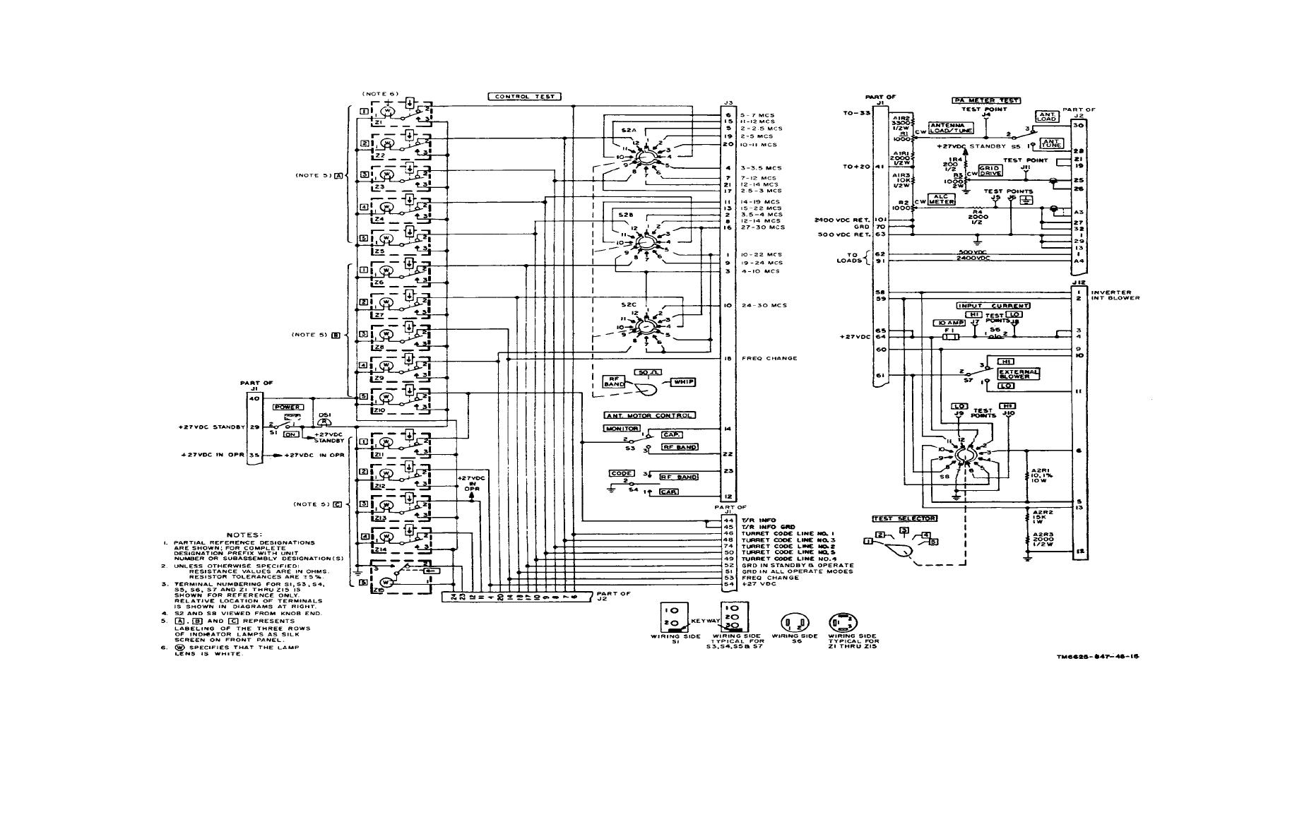
> Figure 6-13. Converter and control tray A1A4, schematic diagram.
Figure 6-12. Synthesizer test tray A1A3, amplifier module AR3, schematic diagram.
Figure 6-14. Driver, discriminator, and antenna coupler tray A1A5, schematic diagram.
TM-11-6625-847-45 Simulator Radio Frequency SM-442A/GRC Manual
Page Navigation
113
114
115
116
117
118
119
120
121
122
123
TM
11-6625-847-45
Figure
6-13.
Converter
and
control
tray
A1A4,
schematic
diagram.
Change
1
6-25


 Previous Page
