TM 11-5840-281-12-1
1-15.
COMPONENT PRINCIPLES OF OPERATION. (CONT)
CONTROL-INDICATOR
The most important function of the control-indicator is to display the radar Information on a crt. When the information is
displayed, the operator must be able to interpret what he or she sees and use the Information to guide an aircraft to the
runway for a safe landing. The use of the controls is described in paragraph 2-1.
PPI DISPLAY
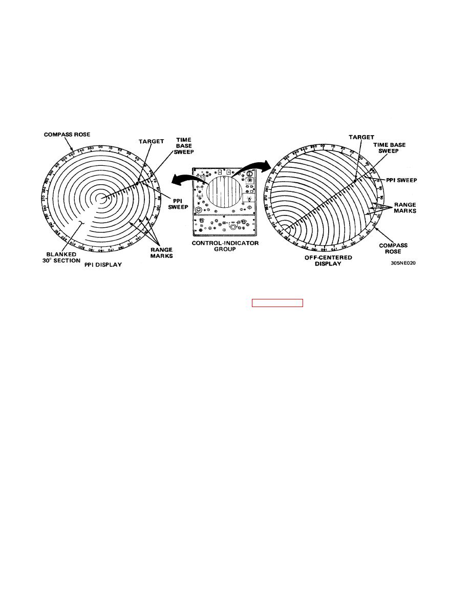
The plan position indicator (ppi) display Is used for search operation when operating in SEARCH, SIMULT, or IFF modes.
The time-base sweep is produced by a point of light that starts at the center of the crt and moves to the outer edge. The
starting time is synchronized with the transmitted pulse that leaves the antenna. The sweep rotates around the crt in
synchronization with the azimuth antenna, approximately 16 revolutions per minute. The antenna receives an echo only
when it is pointing directly at the target, and the echo produces a bright spot on the time-base sweep that represents the
target. The azimuth of the target can be read on the compass rose as the time-base sweep goes past it. Because the
time-base sweep indicates the direction of the beam, and the target position along the sweep indicates the position in
time (hence the range), a maplike picture of the airspace around the radar set is created. Such a display is commonly
referred to as a ppi display.
The ppi display utilizes ranges of 5, 10, 20, 40, and 80 nautical miles. When an 80-mile range is selected, a target is not
displayed, only the IFF return will be seen when operating in conjunction with auxiliary IFF equipment. For 5 and 10-mile
ranges, the range marks will represent 1-mile Intervals, and 5-mile intervals for 20- and 40-mile ranges. A 30-degree
sector of the range marks is blanked to represent the precision approach path (the direction of the approach to the active
runway). This allows the operator to guide the aircraft to the approach end of the runway.
OFF-CENTERED DISPLAY
Normally the center of the ppi display represents the location of the radar set. If necessary, the operator can shift this
central point to one edge of the crt to extend the range in a particular direction by utilizing the PPI CENTERING controls.
1-21


 Previous Page
