TM 11-584-28135/1
turned on, the diagram starts with transistor Q4002 cut
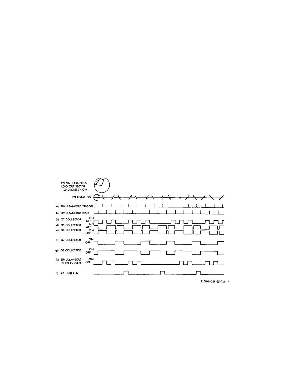
(j) The fourth simultaneous trigger is locked
off, transistor Q4006 cut off, transistor Q4007
out, as indicated by the break in the baseline, and there
conducting, and transistor Q4008 cut off.
can be no AND gate. The fourth reset trigger can switch
(g) Each simultaneous trigger turns on
only the state of transistors Q4005 and Q4006, since
transistor Q4002, as shown in line (c). Each reset trigger
transistor Q4002 is still turned off; but, when transistor
turns off transistor Q4002 and switches the state of
Q4006 is turned on, it switches the state of transistors
transistors Q4005 and Q4006, as shown at lines (d) and
Q4007 and Q4008, as indicated by lines (f) and (g).
(k) As the search antenna scans through
(e). Each time transistor Q4006 conducts, it changes the
state of transistors Q4007 and Q4008 as shown at line
the azimuth sector, the azimuth display is unblanked as
(f) and (g).
indicated by line (i). Note that each time relay K4014 is
There can be no AND gate since transistor Q4008 was
operated, it produces an azimuth relay gate trigger the
turned off during the time transistor Q4002 was
same as when the azimuth microswitch rolls off the cam
conducting.
in precision operation, and the relay gate is switched to
(h) The next simultaneous trigger changes
elevation. Otherwise, slave Control-Indicator C-6988/
the state of transistor Q4002 but does not affect the
TPN-18 is always ready for the azimuth unblanking pulse
other multivibrators. The second reset trigger turns off
to display azimuth. No more than two successive
transistors Q4002 and Q4006 only, but an AND gate is
elevation scans can be displayed and, occasionally, two
produced during the time that transistor Q4002 was
successive elevation scans are not displayed if the third
turned on, since transistor Q4008 was also conducting,
count is followed by a locked-out-trigger.
g. Electronic Filter Circuit (fig. 7-8 and 7-42)
which operated relay K4014 to display an elevation scan.
(i) The third simultaneous trigger turns on
The primary function of the electronic filter circuit is to
transistor Q4002 only, and since transistor Q4008 is still
filter potentiometer noise from the azimuth and elevation
turned on, the AND gate again operates relay K4014 to
angle voltages. Other functions are to present a high-
display the elevation and blank out the ppi. The third
impedance load to the angle data potentiometer, provide
reset trigger turns transistors Q4002 and Q4008 off and
a low output impedance, and provide angle voltage
transistor Q4007 on. When transistor Q4007 conducts, it
phase lead to compensate for phase delay in Control-
turns transistor Q4005 on and transistor Q4006 is turned
Indicator C-6988/TPN-8
off.
Figure 2-19. Simultaneous counter
2-32


 Previous Page
