TM 11-5841-291-12
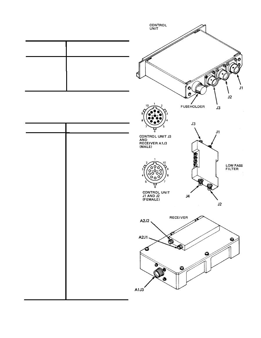
Table 3-2. Control Unit to Receiver
Connections (J1 and J2 to A1J3)
Continued
Connector pin
Signal name or voltage
(J1, J2, and
A1J3)
11
Shield ground
12
Spare
13
Spare
Table 3-3. Control Unit J3 to Aircraft
Interface Connections
Connector pin
Signal name or voltage
1
Remote AI indicator
drive
Remote SAM indicator
2
drive
Audio output (150-ohm
3
load)
Audio return ground
4
5
SAM logic output
AI logic output
6
7
Spare
8
Master caution light
power
Dimming from aircraft
9
console control
Master caution light
10
power
Ground
11
Shield ground
12
+28V power input
13
3-3


 Previous Page
