TM 11-6625-847-45
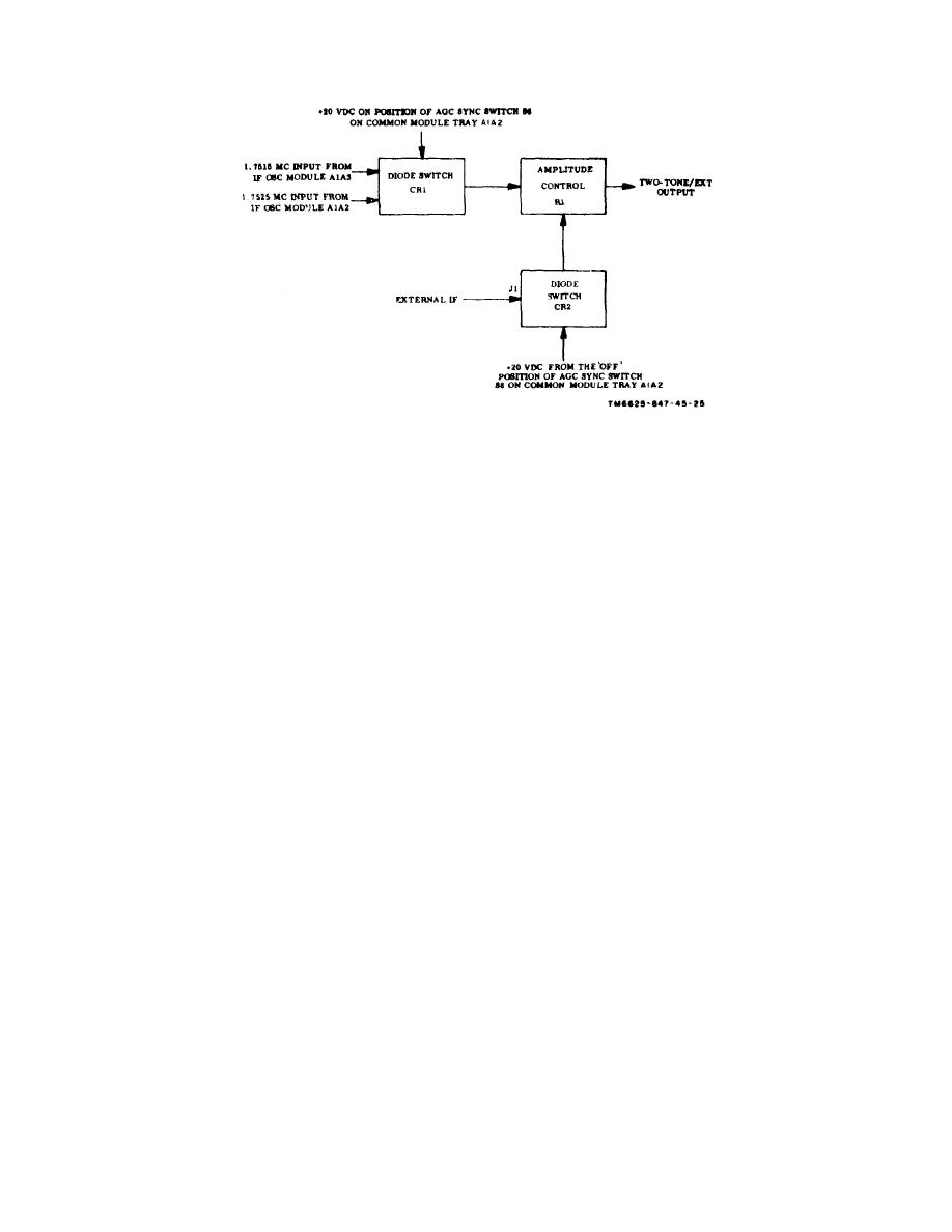
Figure 1-10. Test set mixer assembly, functional block diagram
SERV SEL switch is set at CW 1-12 or FSK, contacts 10
B1 and B2. When the SERV SEL switch is set to OVEN
and 11 of switch A1S1, section A, rear, are open.
ON, the + 27-volt dc primary power is applied through
contacts 1 and 2 of switch A1S1, section A, front, to pin
c. When the SERV SEL switch is set at STBY, the
34 of connector J1. When the SERV SEL switch is set at
required standby ground for PA CONTROL connector pin
STBY, the + 27-volt dc primary power is applied through
N is supplied through contacts 9 and 8 of switch A1S1,
contacts 1 and 3 of switch A1S1, section A, front, to pin
section B, front. When the SERV SEL switch is set at any
29 of connector J1, to contact 9 of REC XMIT switch
operate position (SSB/NSK, CW, AM, FSK), the required
A1S4, and to dc-to-dc converter and regulator module A3.
operate ground for PA CONTROL connector pin P is
This voltage is used in dc-to-dc converter and regulator
applied through contacts 9 and 10 of switch A1S1, section
module A3 to energize the +20-volt dc regulator circuits.
B, front.
When the SERV SEL switch is placed at any operate
d. When the SERV SEL switch is set at SSB/NSK,
position (SSB/ NSK, FSK, AM, CW), the +27-volt dc
the ground on contact 11 of switch A1S1, section B, rear,
primary power is applied to all STANDBY and OVEN ON
is applied through contacts 11 and 12 of switch A1S1
circuits, as previously explained, and through contacts 1
section B, rear, to pin 87 of J1. When the SERV SEL
and 4 of switch A1S1, section A, front, to pin 35 of
switch is set at FSK, ground is applied through contacts
connector J1 and to pin 2 of assembly A1S1 and A1S2.
11 and 1 of switch A1S1 section B rear, to pin 31 of
connector J1. When the SERV SEL switch is set at AM,
b. When the SERV SEL switch is set at CW, the +
the ground is applied through contacts 11 and 12 of
20-volt dc output from transistor Q1 is applied through
switch. A1S1, section B, rear, to pin 87 of connector J1,
contacts 5 and 6 of switch A1S1, section A, rear, to pin 30
and through contacts 11 and 2 of switch- A1S1, section B,
of connector J1. When the SERV SEL switch is set at
rear, to pin 32 of connector J1. When the SERV SEL
SSB/ NSK or AM, pin 75 of J1 is connected through
switch is set at CW, the ground is applied through
contacts 10 and 11 of switch A1S1, section A, rear, to
contacts 11 and 1 to pin 81 of connector J1 and through
contact 10 of switch A1S1, section C, front. When the
contacts 11 and 8 to pin 33 of connector J1.
1-12


 Previous Page
