
TM 11-6625-847-45
shafts of the turret assembly and the BAND SEL control.
Rotating the BAND SEL control positions the turret
assembly to one of three detented positions, 8.25 MC,
15.5 MC, and 29.5 MC, representing the low, middle,
and high ends of the frequency band o the driver
assembly on the AM-3349/GRC2 106. Transformers
T1, T2, and T3, mounted on the turret assembly,
provide the proper impedance loads for the driver
assembly (when mounted on tray A1A5) for the
frequencies selected.
The wiper contacts on the
appropriate transformer mesh with the contacts on the
driver assembly when the turret assembly is In a
detonate position. When the turret assembly is not in a
detonate position (rotating), microswitch A1S1
disconnects the + 200-volt dc B + supply voltage from
Figure 1-16. Gear drive assembly functional block
the driver assembly and extinguishes 200 VDC indicator
diagram
DS2.
SEL control is connected to the turret assembly by a
loop drive -chain connected to sprocket gears on the
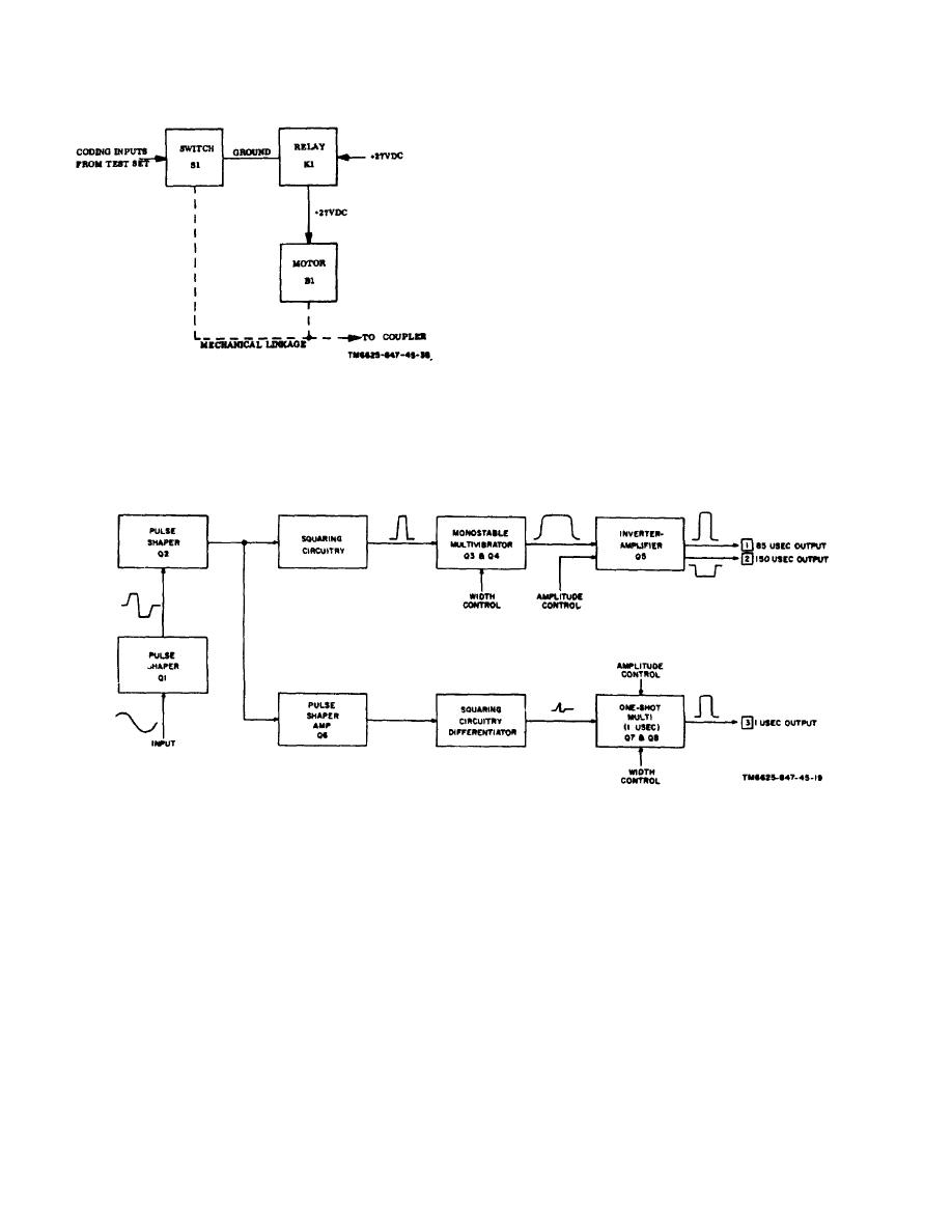
Figure 1-17. Test set pulse generator assembly block diagram.
1-26

 Previous Page
