Home
Download PDF
Order CD-ROM
Order in Print
Home
>
Radar Maintenance and Parts Manuals
>
> Figure 2-12 (1) Switching Units SA-2139 (V3, V4) and SA-2156 (V2) Installation Diagram (Part 2 of 2)
Figure 2-12 (1) Switching Units SA-2139 (V3, V4) and SA-2156 (V2) Installation Diagram (Part 1 of 2)
Figure 2-13. Interface Unit J-3463 Installation Diagram (V2).
TM-11-5840-360-14-1-1 Radar Set AN/SPS-64(V)5 (NSN 5840-01-034-3946) Manual
Page Navigation
84
85
86
87
88
89
90
91
92
93
94
TM
11-5840-360-14-1-1
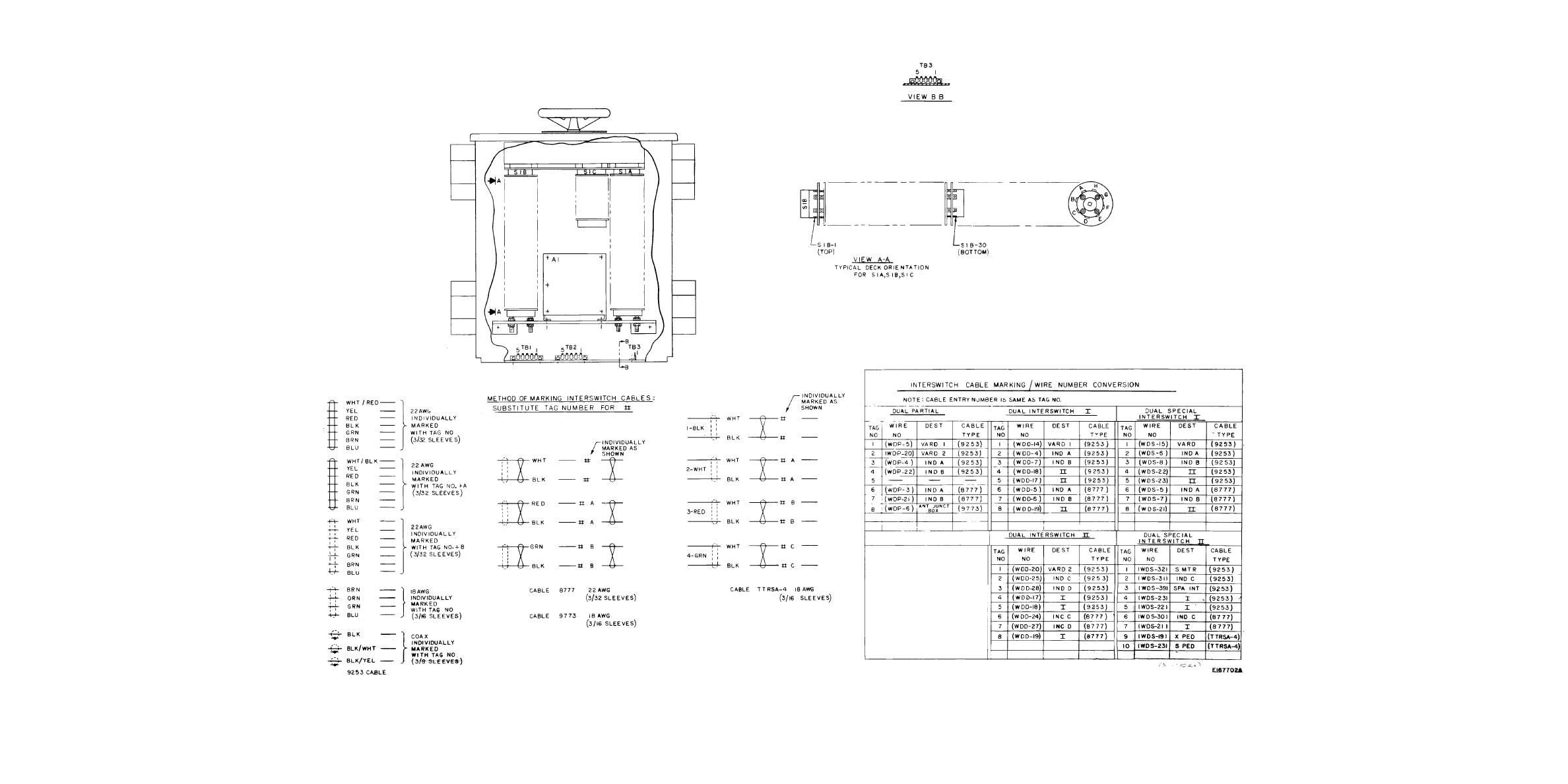
Figure
2-12
(2)
Switching
Units
SA-2139
(V3,
V4)
and
SA-2156
(V2)
Installation
Diagram
(Part
2 of 2)
2-54


 Previous Page
