
TM 11-5840-360-14-1-1
SYMBOL
LEGEND
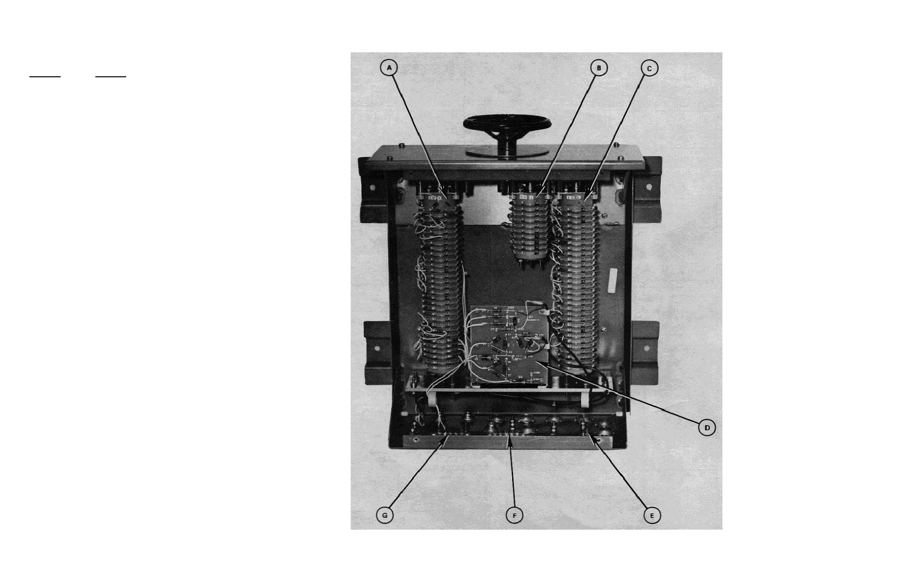
A
Switch Section, S1B
B
Switch Section, S1C
C
Switch Section, S1A
D
Resistor Panel Assembly, A1
E
Terminal Strip, TB3
F
Terminal Strip, TB2
G
Terminal Strip, TB1
Figure 5-10 Switching Units SA-2139 (V3, V4) and SA-2156 (V2) Parts Location
5-67


 Previous Page
