TM 11-5840-281-12-1
2-4. PRELIMINARY CONTROL SETTINGS. (CONT)
1.
Place FTC switch (1) on master control-indicator to OFF position.
2.
Place PPI CENTERING NORM-OFFSET switches (2) on both control-indicators to NORM position.
3.
Place POWER circuit breakers (3) on both control-indicators to OFF position.
4.
Place ANT POL switch (4) on master control-indicator to LIN position.
5.
Place BITE-AZ TILT switches (5) on both control-indicators to AZ TILT position.
6.
Rotate INTENSITY controls (6) on both control-indicators fully counterclockwise.
7.
Rotate FOCUS controls (7) on both control-indicators fully counterclockwise.
8.
Place TRANSMITTER switch (8) on master control-indicator to OFF position.
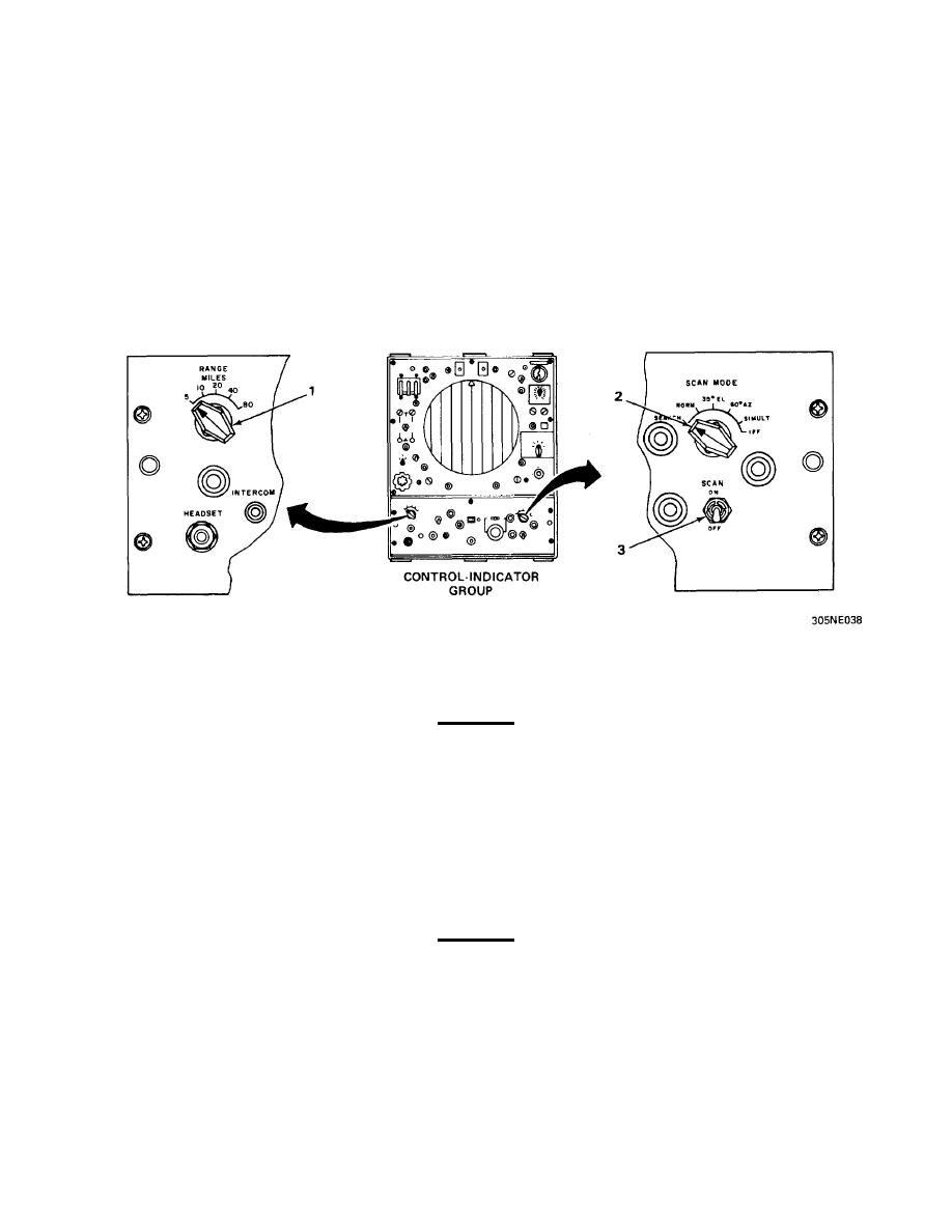
PULSE GENERATOR UNITS
1.
Place RANGE MILES switch (1) on both pulse generator units in any position except 80.
2.
Place SCAN MODE switch (2) on master pulse generator unit in any position except IFF.
WARNING
When used in landing control central systems, the SCAN switch on both pulse generator
units must be in OFF position to prevent inadvertent antenna scan operation, and possible
injury to personnel.
3.
Place SCAN switch (3) on both pulse generator units to OFF position.
2-5. PRELIMINARY OPERATING PROCEDURE.
TURN-ON PROCEDURE
WARNING
Lethal voltages are developed in the receiver-transmitter and control-indicators. Observe
safety precautions at all times.
2-13


 Previous Page
