TM 11-5840-281-12-1
4-8.
ANTENNA PEDESTAL ASSEMBLY. (CONT)
2.
Remove two retaining bolts (3) from each of three bottom retaining straps (4) and two retaining bolts (5)
from each of three top retaining straps (6) and remove straps.
3.
Unbolt three bottom (4) and three top retaining straps (6) securing three leg assemblies (1).
4.
On each leg assembly (1) loosen, but do not remove, four screws (7) securing two retaining hinges (8).
5.
Lower each leg assembly (1) by sliding It away from the center section (2) and then swinging it down.
6.
Using five bolts (9), flat washers (10), and lockwashers (11), secure each leg assembly (1) to center section
(2).
7.
On each leg assembly (1), tighten four screws (7) loosened in step 4, in two retaining hinges (8).
4-9.
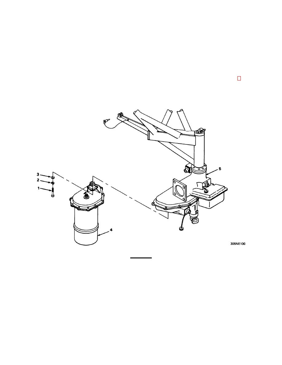
AZIMUTH ANTENNA DRIVE ASSEMBLY.
MATERIALS/PARTS: Cloth sack marked AZIMUTH ANTENNA DRIVE HARDWARE
CAUTION
To prevent damage to rotary joint waveguide, turn azimuth antenna yoke assembly so
curved portion of rotary joint waveguide Is facing away from azimuth antenna drive.
Using four bolts (1), lockwashers (2), and flat washers (3), secure azimuth antenna drive reducer (4) to azimuth antenna
drive (5).
4-23


 Previous Page
