TM 11-5840-281-12-1
4.27. PRELIMINARY SERVICING AND ADJUSTMENT. (CONT)
AZ TILT/BITE METER ALINEMENT (CONT)
5.
On AZ-EL blanking pulse generator card, adjust R36 METER ZERO control for - 1 degree indication on AZ
TILT/BITE meter.
6.
Using ANTENNA switch, adjust clinometer to indicate + 20 degrees and tilt azimuth antenna until clinometer
bubble indicates level.
7.
On AZ-EL blanking pulse generator cord, adjust R36 METER ZERO control for + 20 degree indication on AZ
TILT/BITE meter.
8.
Place BITE-AZ TILT switch on control-indicator to BITE position.
9.
Set multimeter to measure + 5 v. Connect negative lead of multimeter to J616 DC RET and positive lead to
J615 BITE MON on control indicator front panel.
10.
Place BITE SELECT switch to CALIBRATE position.
CAUTION
Make sure adequate support is available so pulse generator does not fall when being pulled
out of control-indicator.
11.
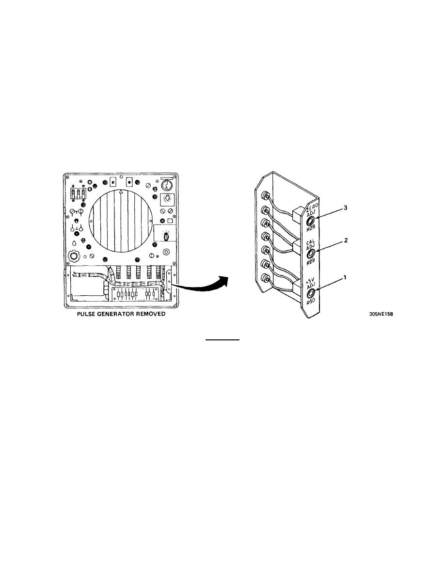
Pull pulse generator out of control-indicator until R30 + 5V ADJ (1) is accessible. Adjust R30 for multimeter
Indication of + 5 v.
12.
Adjust R29 CAL ADJ (2) for full-scale AZ TILT/BITE meter indication.
13.
Place BITE SELECT switch to ZERO position.
14.
Adjust R28 ZERO ADJ (3) for exact center scale AZ TILT/BITE meter indication.
15.
If necessary, repeat steps 12 through 14 to obtain full-scale and center-scale AZ TILT/BITE meter Indications.
16.
Disconnect multimeter leads, reinstall pulse generator, allowing access to top deck controls. Place BITE-AZ
TILT switch to AZ TILT position.
4-82


 Previous Page
