TM 1 1-5840-281-35/1
Control settings
Step No.
Test equipment
Equipment under test
Test procedure
Performance standard
1292/TPN-8 by hand through one
360-deg scan. Observe that
there is no excessive pulling of
magnetron frequency. Any
pulling of magnetron frequency
due to change in load impedance
will cause corresponding
horizontal shift of spectrum
pattern.
a. Height of main
a.
On spectrum analyzer,
8
As last indicated ............
As last indicated, except:
lobe is at least
compare height of main lobe to
Master Control-Indicator
twice the height of
height of first side lobe on both
C-6988/TPN-18
side lobes.
sides of main lobe (fig.
ANT POL: CIR
b. Spectrum pattern
b.
Check spectrum pattern for
is stable with no
missing vertical prf lines , and
missing ptf lines.
stability.
c. None.
c.
Place ANT POL switch to LIN.
d. None.
d.
Replace rear cover on Radar
Receiver-Transmitter
RT818/TPN-18 and disconnect
spectrum analyzer.
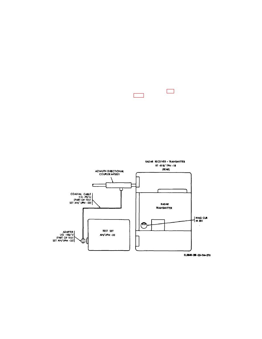
Figure 5-26. Magnetron spectrum test connections.
5-72


 Previous Page
