TM 11-5840-360-14-1-1
INSTALLATION INSTRUCTIONS
3
A2J4
I.
The Indicator that T M is to be installed n must have the following options installed
4
TM U Ac input to TB4 10, 11 & 12
and operating
H
Connect Speed Log Cables to TB4
A
NSK
*
I.
Install and wire A9R-5
B
EBL
*
J
Install and wire joystick assy
C
VRM
*See NSK/joystick jumper kit. 165835
Also, the indicator must be aligned properly, in particular the sweep generator PCB A2A10
K..
Plug T M U harness to TMU card basket assy, and install card basket indicator
II..
The TMU consists of the following major assemblies
L..
Reinstall the indicator power supply the indicator card basket. the NSK assy and the sweep output assy
A
Head Set Assy
M.
Remove EBL card (A2A9) and link as necessary for TMU option
B.
Power Supply Assy
BRD91 PIN 589468-2 REV C
C.
Card Basket Assy
1.
Link E2 to E4
D.
Joy Stick Assy
2
Link EB to El
E.
Sine-Cosine Pot (A9-R 5)
3
Link E14 to E15
III.
Mechanical Assembly
4.
Link E18 to E19
A.
Remove Indicator Power Supply
Reinstall EBL card (A2AB)
B.
Remove the 2 Cover Pirates On The Top Rear of Indicator
BRD PIN 5894682 REV D&E
C.
Remove Indicator Card Basket
1.
Link E2 to E4
1.
Check that there is a wire from A2J4 60 to A2A11 28. A2J4 59 to A2A11 F
2.
Link E8 to E10
2.
Check A2J4-6 to J6-V A2J4-9 to J6-W
3.
Link E14 to E15
D
Swing down Sweep output assembly and NSK if already installed In Indictor
4.
Link E18 to E19
E.
Drop TMU harness through the left side headset mounting ho e and bolt
5
Link E16 to E17
headset assy in place
N
Remove Offset Switch and Offset Switch Lamp Cover ends of wires with Shrink
F.
Mount TMU power supply on left side of indicator in the space provided.
Sleeving
G.
Connect TMU harness to:
O
Install Offset Switch Cover P ate
1.
Power Supply
IV
REFER TO MANUAL FOR FURTHER INSTALLATION NSTRUCTIONS
2.
J-6
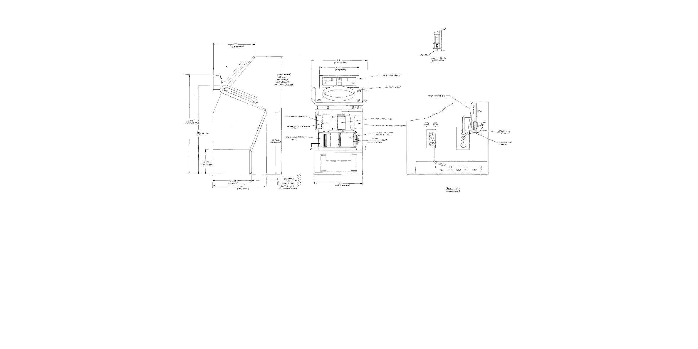
Figure 2-1. Radar Set AN/SPS-64(V)1 Cabling Diagram.
2-7


 Previous Page
