TM 11-5840-360-14-1-1
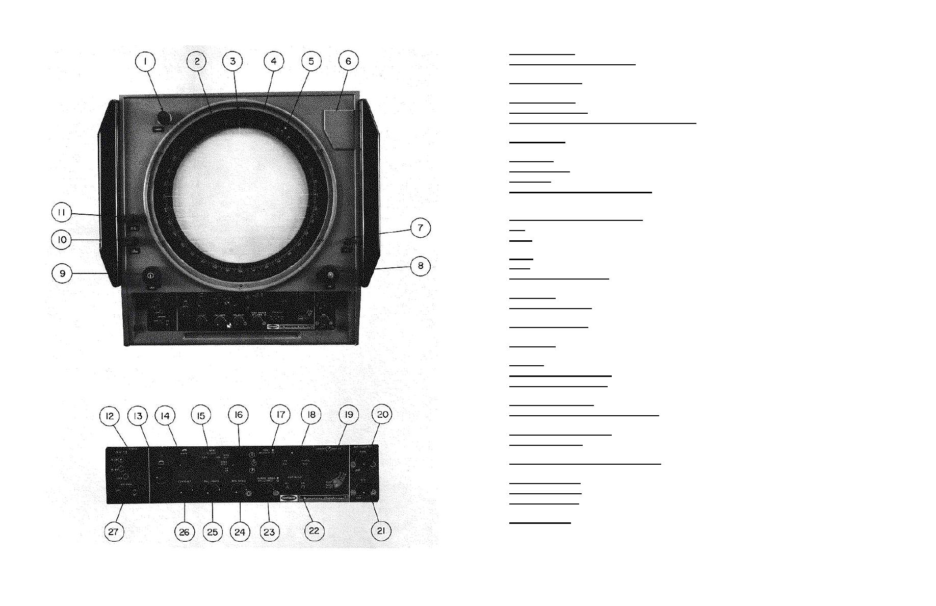
1 COMPASS Control - Rotates true bearing ring (4) when TBK is not in use.
2 Range Scale and Markers Indicators - Each of these 11 lamps lights to indicate the range scale and corresponding
markers selected by the RANGE SELECT switch (20).
3 VRM Digital Readout - Provides range reading corresponding to size of VRM ring on PPI screen and range scale in
use.
4 True Bearing Scale - Indicates true bearing of ship when TBK is in operation.
5 Relative Bearing Scale - Provides indication of relative bearing.
6 EBL ORIGIN Joystick and TGT MARK Pushbutton - Joystick positions EBL origin on selected echo return.
Pushbutton places target mark on desired echo return. Use with true motion.
7 OFFSET Switch - Provides expanded view of area ahead of ship by offsetting ship's position by 70 percent of CRT
radius (astern direction). No offset is available on 48 or 64 mile ranges.
8 VRM Control - Adjusts size of VRM ring displayed on CRT.
9 CURSOR Control - Provides 3600 rotation of cursor cross-hair graticule.
10 EBL Control - Controls azimuth position of the EBL.
11 EBL DIM Control and EBL READ Switch - EBL DIM (inner knob) adjusts the brightness of the EBL. In the offset
mode of operation, the EBL READ switch (outer knob) is turned CW to return EBL origin to center of CRT display to provide
correct bearing readings.
12 POWER Switch and Transmit Indicator -
OFF - Turns the radar off.
ST BY - Radar is operational after approximately 3.5 minutes. Transmit indicator flashes as long as the switch is in
this position.
TX ON - Radar is fully operational when indicator glows steadily.
PERF - Enables performance monitor.
13 TUNE Control and Indicator - TUNE control is adjusted for maximum average brightness on the indicator and
maximum echo return displayed on the PPI.
14 GAIN Control - Sets signal level. Normally adjusted to provide slight background "speckle".
15 INTRF REJECT Switch - Cancels the display of interference from other radar equipped vessels operating within
reception range.
16 NSK Function Switch - HD UP - Orients PPI map so that radar returns from directly ahead of ship appear at 00 on
the relative bearing scale (5). The heading line flash also appears at 00.
GYRO STAB - Orients PPI map so that radar returns from true north appear at 0 on the relative bearing scale,
heading line flash indicates ship's true heading.
HDG SET - Momentary (spring-loaded to GYRO STAB); used to set heading flash to ship's true heading.
17 VRM and READOUT Controls - Adjust intensity of VRM ring and intensity of VRM digital readout (3).
18 FTE ON/FLASH OFF Switch - Cancels heading line flash in the FLASH OFF position. Enables false target detection
circuit in the FTE ON position.
19 RANGE SELECT Switch - Selects any of 11 available ranges.
20 ANTI-CLUTTER RAIN Control and Switch - Reduces unwanted fill-in of larger echoes such as areas of heavy
precipitation of land masses. Function is switched off when control is fully CCW.
21 ANTI-CLUTTER SEA Control - Suppresses PPI display of reflections from nearby wavetops and heavy spray.
22 PWR BOOST Switch - When held in the ON position, changes system operation from short to medium pulse on 3-
mile range to enhance display of small nearby objects.
23 RANGE RINGS and BRILLIANCE Controls - Control intensity of range marker rings and brightness of displayed
video.
24 BRG SCALE Control - Adjusts intensity of true bearing scale (4) and relative bearing scale (5).
25 PNL LIGHTS Control - Adjusts intensity of panel illumination lamps and plotter intensity.
26 CONTRAST Control - Selects video threshold to determine brightness level at which each signal return echo will be
displayed on the PPI.
27 ANTENNA Switch - Spring-loaded normally ON switch applies rotational power to the antenna motor. Stops antenna
rotation when held in the OFF position.
Figure 3-2 Indicators IP-1282/IP-1283 Operating Controls
3-9


 Previous Page
