TM 11-6625-1831-13
CHAPTER 2
INSTALLATION AND OPERATING INSTRUCTIONS
Page
Page
Chapter Overview
...................................................2-1
Operating Procedure.................................................2-10
Service Upon Receipt ..................................................2-1
Preparation for Movement ........................................2-10
Description and Use of
Operation In Unusual
Operator's Controls and
Environment ..............................................................2-10
Indicators ...................................................2-1
Emergency Procedures.............................................2-10
Service Upon Receipt........................................2-5
Operator/Crew Maintenance ..................................2-11
Operation
...................................................2-6
Introduction ...............................................................2-11
Assembly and Preparation
Operator/Crew PMCS ...............................................2-11
for Use ...................................................2-6
Operator/Crew Maintenance .....................................2-12
Unpacking Instructions ......................................2-6
Installation and Preparation
for Use ...................................................2-8
CHAPTER OVERVIEW
This chapter tells you how to get the test set ready for use and how to use it and take care of it under various operating
conditions.
Section I.
SERVICE UPON RECEIPT
2-1
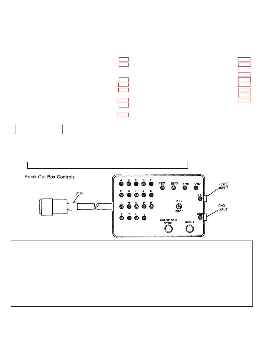
DESCRIPTION AND USE OF OPERATOR'S CONTROLS AND INDICATORS
A-V test jacks -- Allow checking of signals from
+5, GND test jacks - Allow checking of 5 volt power
signal processor DDL interface
supply input
DTG1, DTG2 jacks - Not used
PULSE GEN SYNC jack - Provides sync signal for
pulse generator
F/R1, F/R2 jacks - Not used
INPUT jack - Input from pulse generator
DDL-PROC switch - Controls output of signal
processor DDL interface during test
+5 VDC INPUT, GND INPUT jacks - Input from 5
volt power supply
2-1


 Previous Page
