TM 11-6625-847-45
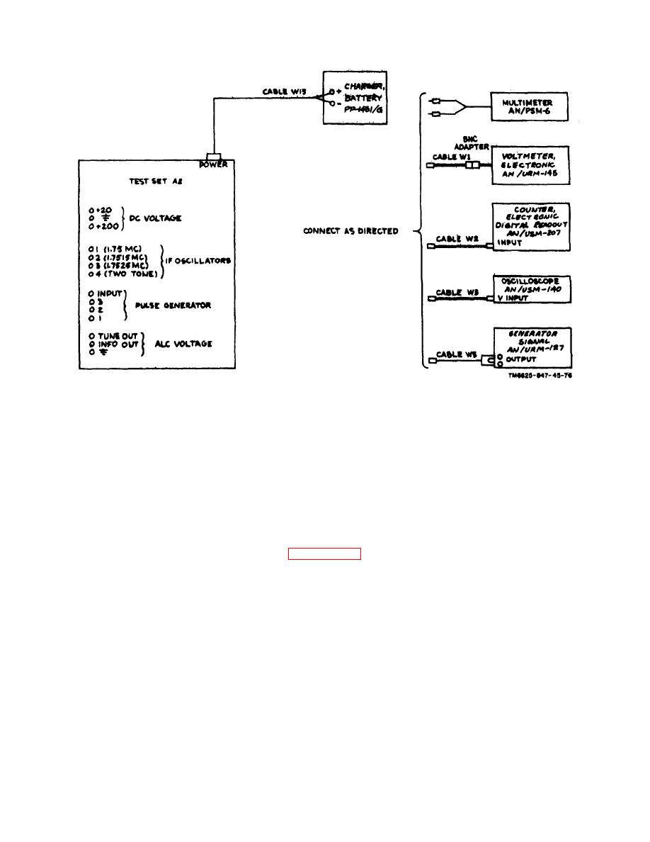
Figure 5-1. Test set operational performance test setup.
5-9. Common Module Tray A1A1, Operational Performance Test
Note. The ME-26(*)/U is the only piece of test equipment required for this test.
Step
Control setting and operation of
No.
Operation of test procedure
equipment under test
Performance standard
1
Remove common module tray
A1A1 from case 2, and se-
cure it to the test set.
2
Make sure that +27-
Set the switches and controls
volt dc primary
on the test set to the positions
power is supplied to
listed in paragraph 5-6. Set
the POWER connec-
the switches and controls on
ter on the test set.
common module tray A1A1
to the settings listed in par-
graph 5-8.
3
Set the POWER switch on the
POWER indicator on test set
test set to ON. Set the POWER
is illuminated
switch on common module tray
A1A1 to ON.
4
Measure the dc voltage
Rotate the SERV SEL switch
Measured is +27 1
at DC/DC CONVER-
on the test set to SSB/NSK.
dc; POWER indicator on
TER test points HI
common module tray A1A1
and LOW on tray
is illuminated.
A1A1 using the ME-
26(*)/U.
5-4


 Previous Page
