
TM 11-5840-281-12-1
CHAPTER 2
OPERATING INSTRUCTIONS
Subject
Section
Page
Description and Use of Operator's Controls and Indicators ..........................................
Operator Preventive Maintenance Checks and Services (PMCS) ................................
Operation Under Usual Conditions ..............................................................................
Operation Under Unusual Conditions ...........................................................................
Section I DESCRIPTION AND USE OF OPERATOR'S CONTROLS AND INDICATORS
2-1.
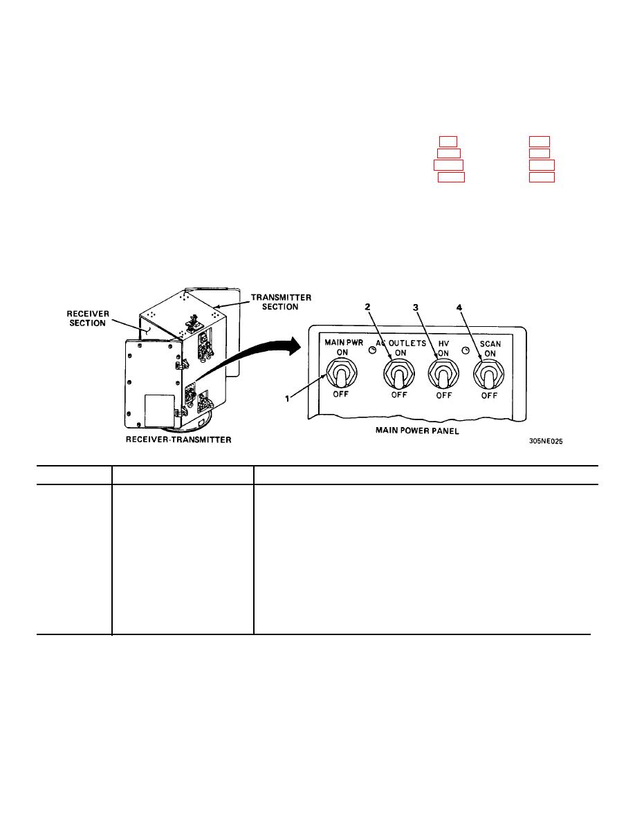
FUNCTIONS OF CONTROLS, SWITCHES, AND INDICATORS.
RECEIVER-TRANSMITTER
KEY
CONNECTOR
FUNCTION
1
MAIN PWR circuit breaker
Applies primary 120 vac, 3-phase, 400 Hz power to
receiver-transmitter.
2
AC OUTLETS circuit breaker Applies 120 vac, single-phase, 400 Hz power to ac
outlets.
3
HV switch
Applies + 28 v enable voltage to interlock transmitter
high-voltage power supply.
4
SCAN switch
Applies primary ac power to scan drive motors.
2-1

 Previous Page
