TM 11-5840-281-12-1
4-5.
SITE AND SHELTER REQUIREMENTS. (CONT)
RUNWAY SITING CONFIGURATIONS (CONT)
305N E079
NOTE
Runway numbers usually, but not always, indicate magnetic heading of runway. Therefore,
the number 18 indicates a magnetic heading of 180 degrees for that runway.
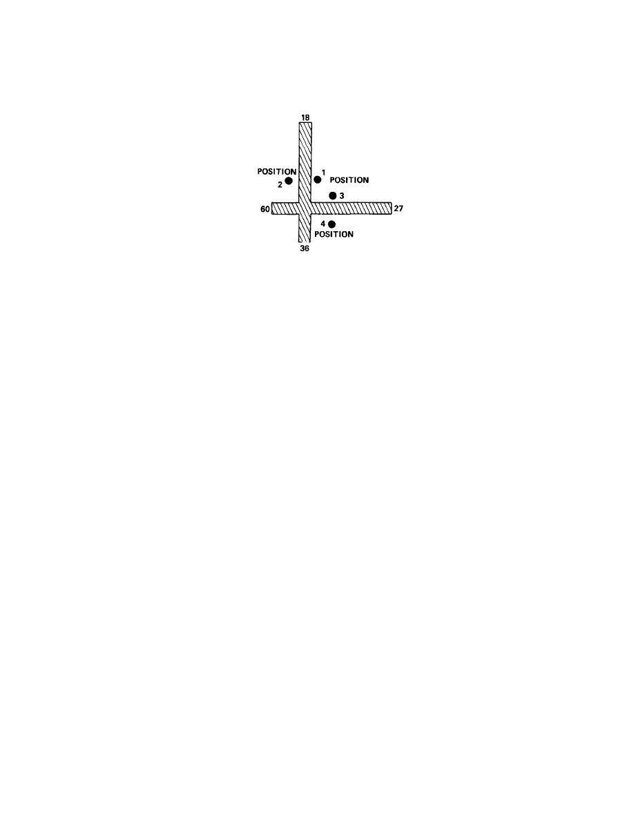
It is difficult to cover all four approaches to two runways when they form right angles by intersecting at offcenter points,
as shown In the figure above. Positions 1 and 2 readily cover runways 18, 27, and 36, but are too close to the end of
runway 09 to provide proper coverage. Positions 3 and 4 provide complete coverage for runways 09, 18, and 27 but are
too close to the end of 36 to provide adequate coverage.
EQUIPMENT COMPONENT LOCATION
NOTE
Refer to TM 11-5895-474-12 addendum for location of components and routing of
interconnecting cables when installing radar set in Landing Control Central AN/TSQ-71 B.
Control Indicator Group
When not installed as part of a landing control system, the two control-indicator groups may be located up to the
maximum distances permitted by interconnecting cables. The video, control data, and pretrigger cables (W3001,
W3002, and W3005) connecting the master control-indicator group to radar set group are 250 feet long; the ac power
cable (W3003) connecting the master control-indicator group to the ac power distribution box is 135 feet long. The
power, video, control data, and pretrigger cables (W9501, W9502, W9503, and W9504) connecting the slave control-
indicator group to the master control-indicator group are 25 feet long.
Primary AC Power Generator and AC Power Distribution Box
The primary ac power generator (not part of radar set or landing control system) must be easily accessible for refueling.
The ac power distribution box must be within 8 cable feet of the primary ac generator and within 135 cable feet of
receiver-transmitter group and master control-indicator group to allow connection of ac power cables W3003, W3004,
and W3007.
4-8


 Previous Page
