TM 11-5840-281-12-1
4-28. CIRCUIT ALINEMENT. (CONT)
CURSOR ALINEMENT (CONT)
20.
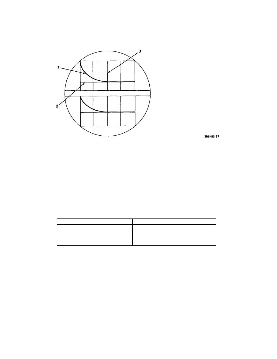
Alternately place ANGLE VOLTS switch in EL and OPERATE positions. Adjust HF2 control to position height
finder cursor (1) at intersection of artificial sweep (2) and 10-mile range mark (3).
21.
Repeat steps 16 through 20 until height finder cursor (1) is alined as indicated in both steps 17 and 20.
PPI DISPLAY ADJUSTMENT
NOTE
Unless otherwise indicated, perform the following steps on control-indicator where ppi
display adjustments are being performed.
1.
On both pulse generators place the switches below to the positions indicated.
SWITCH
POSITION
SCAN MODE switch
SEARCH
RANGE MILES switch
5
SCAN switch
ON
4-100


 Previous Page
