TM 11-5840-281-12-1
4-46.
AZIMUTH ANTENNA SCAN ADJUSTMENT.
TOOLS: Stopwatch or wristwatch capable of measuring seconds
PERSONNEL REQUIRED: Two
PRELIMINARY PROCEDURE:
Perform preliminary control setting (para 3-6).
1.
On local control monitor, place LOCAUREMOTE switch to RT position and SCAN MODE switch to
2.
On receiver-transmitter main power panel, place SCAN switch to OFF position.
3.
On preamp control card, in receiver-transmitter, adjust R8 AC GAIN control clockwise until azimuth antenna
oscillates, then adjust control counterclockwise until antenna stops oscillating. The control should be set as far
clockwise as possible without causing oscillation.
4.
On local control monitor, place SCAN MODE switch to SIM position.
5.
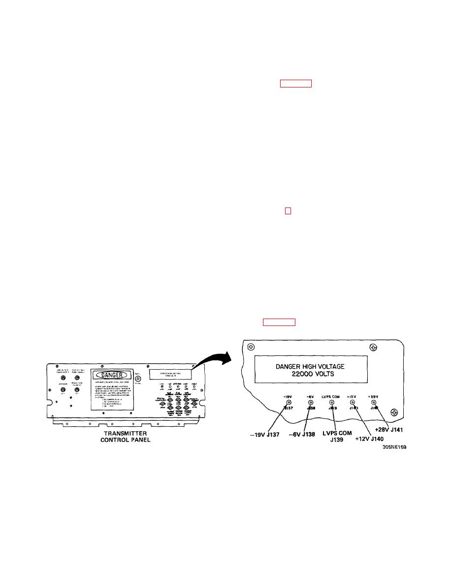
Open transmitter control panel to expose remote switching control.
6.
Direct second person at control-indicator site to place POWER switch on master control-indicator to ON position.
7.
On remote switching control, adjust R59 SEARCH RPM control so that blanked sectors, located on ppi display of
master control-indicator, rotate counterclockwise in sequence and do not overlap from one rotation to the next.
This should occur at a rotational speed of approximately 16 rpm.
8.
Close transmitter control panel.
9.
On receiver-transmitter main power panel, place SCAN switch to OFF position.
10.
On local control monitor, place LOCAUREMOTE switch to IND position.
4-47.
PERFORMANCE TESTS.
The following performance tests should be performed by organizational personnel at periodic intervals as prescribed in
the organizational PMCS table. These tests are conducted so that any possible equipment degradation can be detected
before equipment failure occurs. The tests are divided into eight parts, with each part testing a specific component. If
equipment malfunction is detected, reference is made to the appropriate corrective action. Personnel are listed only if a
task requires more than one technician.
LOW-VOLTAGE POWER SUPPLY TEST
TEST EQUIPMENT REQUIRED:
Multimeter TS-352 B/U or AN/USM-223
TEST CONDITIONS: Radar set turned on, Preliminary Control Settings (para 2-4).
4-143


 Previous Page
