TM 11-5840-281-12-1
4-47. PERFORMANCE TESTS. (CONT)
LOW VOLTAGE POWER SUPPLY TEST (CONT)
CONTROL SETTINGS
TEST PROCEDURE
INDICATION
Set up multimeter to measure
a. On transmitter control
a.
Multimeter indication of
+ 28 vdc. On receiver transmit-
panel, connect positive
+ 28 4 vdc. If
ter main power panel, place MAIN
lead of multimeter to
indication is incorrect,
POWER switch to ON position. On
+ 28V J141 and connect
see paragraph 4-40.
transmitter control panel, place
negative lead to LVPS
LOW VOLTAGE POWER SUPPLY and
COM J139.
MAGNETRON FILAMENT switches
to ON position.
b. Remove positive lead of
b. Multimeter Indication of
multimeter from + 28V
+ 12 + 0.6 vdc. If
J141 and connect to
indication is not correct,
+ 12V J140.
see paragraph 4-40.
Disconnect test leads and
Connect positive lead of
Multimeter indication of
set up multimeter to measure
multimeter to LVPS COM J139
- 19 + 1.5 vdc. If incorrect
- 20 vdc.
and connect negative lead
indication is obtained, see
to - 19V J137.
Set up multimeter to measure
Remove negative lead of
Multimeter indication of
- 10 vdc.
multimeter from -19V J137
- 6 + 0.03 vdc. If indication
and connect to - 6V J138.
is incorrect, see paragraph
4-40.
Disconnect test leads.
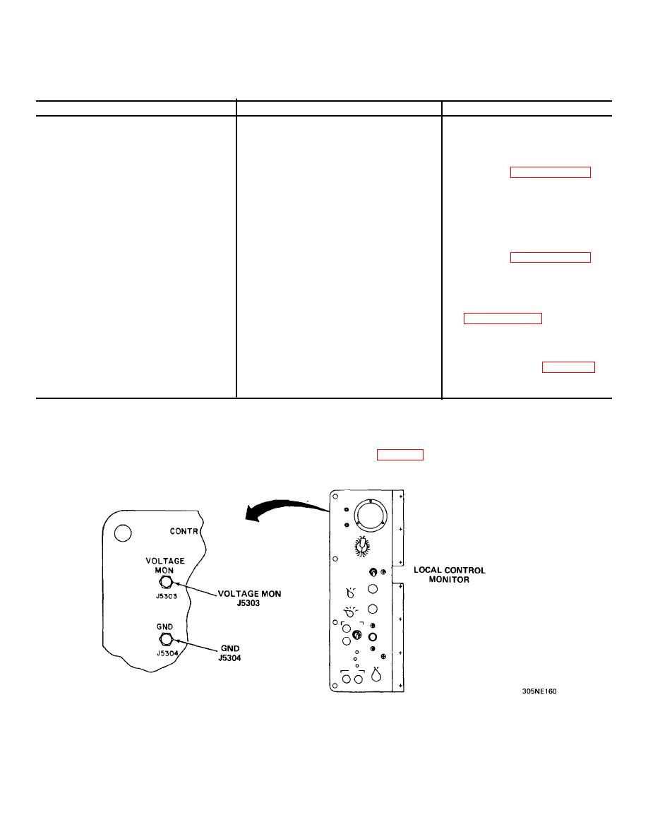
LOCAL CONTROL MONITOR TEST
TEST EQUIPMENT REQUIRED: Multimeter TS-325 B/U or ANIUSM-223
TEST CONDITIONS: Radar set turned on, Preliminary Control Settings (para 2-4).
4-144


 Previous Page
