TM 11-840-281-35/1
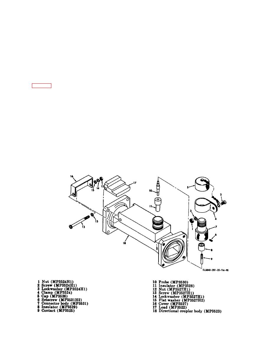
(5) Remove nut (12), screw (13), lockwasher
NOTE
(14), and two flat washers (15).
Shims (6) should be added or removed
(6) Remove cover (16) and load (17) from
to provide minimum end play without
directional coupler body (18).
binding.
b. Assembly. To assemble directional coupler,
proceed as follows:
(6) Secure preformed packings (1) to elevation
rotary coupler to prevent loss until installed on
operational radar set.
NOTE
Cover (16) is to be cemented to
directional coupler body and the
5-23.
Disassembly and Assembly of Directional
attaching hardware encapsulated with a
Coupler
rigid-ratio mixture of Resiweld no. 7004
or equivalent after installation.
a. Disassembly. To disassemble directional coupler,
(1) Install load (17) and cover (16) on directional
proceed as follows:
coupler body (18) using nut (12), screw (13), lockwasher
(1) Remove nut (1), screw (2), lockwasher (8)
(14), and two flat washers (15).
and clamp (4).
(2) Install insulator (11) in directional coupler
(2) Remove cap (5).
body (18).
(3) Remove two setscrews (6) and unscrew
(3) If contact (9) and probe (10) are separated,
connector body (7).
solder together before installing in directional coupler
(4) Remove insulator (8), contact (9), probe (10),
body (18).
and insulator (11).
(4) Install insulator (8) with deepest counter-bore
toward
insulator
(11)
and
screw
connec-
NOTE
Contact (9) and probe (10) are soldered
together, unsolder only if one requires
replacement.
Figure 5-19. Directional coupler, exploded view.
5-60


 Previous Page
