TM 11-584-281-35/1
(2) Fill grease reservoir (17) with grease per
5-25.
Disassembly and Assembly of Receiver-
MIL-G-23827.
Transmitter Case Blower
(3) Place spacer (15) in endbell (21).
(4) Place preformed packing (23) on stator (22)
and align endbell (21) to stator.
a. Disassembly. To disassemble the receiver-
(5) Place bearing (16) on rotor (14) and insert
transmitter case blower, proceed as follows:
into stator endbell assembly.
(1) Remove two setscrews (1) and impeller (2).
(6) Place bearing (20), spacer (19), spring
(2) Remove eight screws (3), lockwashers (4),
tension washer (18), and grease reservoir (17) on rotor
and two motor mounting legs (5).
shaft.
(3) Remove flexible nipple (6), four screws (7),
lockwashers (8), and terminals (9).
NOTE
(4) Remove four screws (10), end bell (11), and
Open side of grease reservoir should
preformed gasket (12).
face toward end of rotor shaft.
(5) Remove retaining ring (13) from end bell.
(6) Pull rotor (14) from housing and remove
(7) Place preformed packing (12) on stator (22)
spacer (15), bearing (16), grease reservoir (17), spring
and install endbell (11) on motor assembly.
tension washer (18), spacer (19), and bearing (20) from
(8) Secure endbells and stator in place with four
rotor.
screws (10).
(7) Separate end bell (21) from stator (22) and
(9) Install each motor mounting leg (5) on motor
remove preformed packing (23).
with two screws (3) and lockwashers (4).
b. Assembly. To assemble receiver-transmitter case
(10) Install four terminal lugs (9) to motor
blower, proceed as follows:
assembly with screws (7) and lockwashers (8).
(1) Install retaining ring (13) in endbell (11).
(11) Place flexible nipple (6) over terminal lugs.
(12) Install impeller (2) on rotor shaft using two
setscrews
(1).
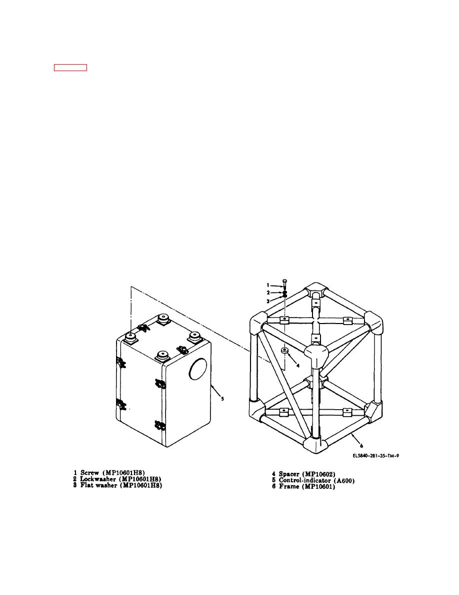
Figure 5-22. Control-indicator group, exploded view.
5-64


 Previous Page
