TM 11-5840-360-14-1-1
2. Connect oscilloscope at collector of Q9 on
6. Adjust R23 on Al100 PCB to obtain 500 nsec
A1300 Control PCB.
between leading and trailing edges at zero Vdc.
3. Verify period between leading edges of
7. Set master Indicator RANGE SELECT switch to
negative-going trigger pulses is 58 1 used (16.95 to
24 MILES and repeat step 3.
17.55 kHz).
8. Adjust R25 on A1100 PCB to obtain 1000 nsec
4. If incorrect adjust R40 on A1300 PCB to obtain
between leading and trailing edges at zero Vdc.
correct period.
5.10.3.2 Power Module Output Voltage Adjustment. -
5.10.3.4 High Voltage Adjustment. - Set the output from
Check and align power module output voltages as
the high voltage regulator as follows:
follows:
1. At master Indicator:
1. Set master Indicator POWER switch to ST BY.
a. Set POWER switch to TX ON.
2. Connect multimeter, set for 1000 Vdc
b. Set RANGE SELECT switch to 24 MILES.
measurement, as follows:
c. Allow 3.5-minute turn-on time delay.
a. Positive lead: TP10 (ground)
2. Connect multimeter, set to 10 Vdc scale,
b. Negative lead: TP1 (-470)
between TP7 (+) and TP10 (-).
3. Adjust R6 on A1300 Control PCB to obtain -465
Vdc reading on multimeter.
WARNING
4. Connect multimeter as indicated in Table 5-3
REGULATED 400 VDC PRESENT
and verify correct dc voltage at each test point (TP10 is
ground).
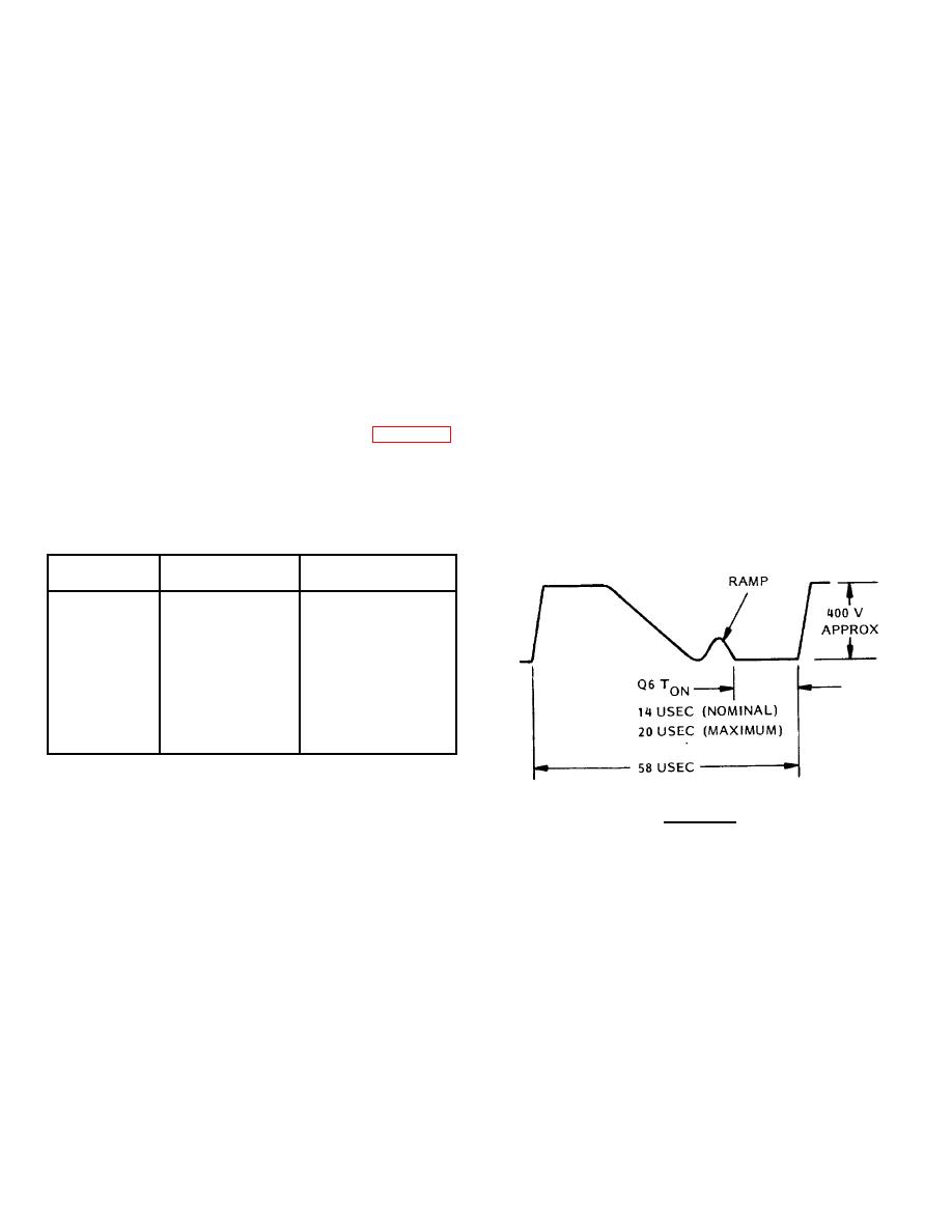
3. Connect oscilloscope between ground and
collector of Q6 on A1200 power module assembly;
Table 5-3 Receiver Transmitter RT-1240
adjust for display of waveform similar to that shown
Power Supply Test Points
below.
POSITIVE
NEGATIVE
DC
LEAD
LEAD
VOLTAGE
TP10O
TP1
-465 5
TP10O
TP2
-12.5 0.5
TP3
TP10
+5 0.25
TP4
TP10
+12.5 0.5
TP5
TP10
+120 10
5.10.3.3 Pulse Width Adjustments. - Set the three
transmitter pulse widths per the following steps:
CAUTION
1. At master Indicator:
DURING THE FOLLOWING STEP, DO
a. Set POWER switch to TX ON.
NOT ALLOW THE ON TIME OF Q6
b. Set RANGE SELECT switch to 1.5
(Q6 TON) TO EXCEED 20 USEC.
MILES.
c. Allow 3.5-minute warm-up time delay.
4. While monitoring the oscilloscope waveform,
2. Connect oscilloscope probe at junction of R39
adjust R57 on A1300 Control PCB to obtain the
and CR3 on A1100 Pulse/Driver PCB.
multimeter reading given below in accordance with the
3. Adjust oscilloscope to display leading and
type of magnetron installed:
trailing edges of the modulator drive pulse at the point
a. Raytheon magnetron: 3.0 to 3.5 Vdc
where they pass through zero Vdc.
b. Toshiba magnetron: 3.0 to 3.5 Vdc
4. Adjust R28 on A 100 PCB to obtain 110 nsec
c. EEV magnetron: 3.5 to 4.0 Vdc
between leading and trailing edges at zero Vdc.
5. Set master Indicator RANGE SELECT switch to
5.10.3.5 Power Module Duty Cycle Limit Adjustment.
6 MILES and repeat step 3.
5-21


 Previous Page
