TM 11-6625-1831-13
5-2b.
Electrical Test of Test Panel (Cont)
LOCATION/ITEM
ACTION
REMARKS
102.
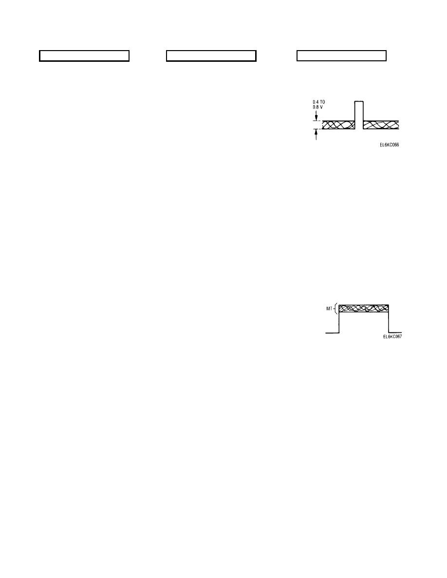
Measure amplitude of doppler sine
Malfunction 47
wave-should be 0.4 to 0.8V. See
illustration.
103.
TEST PANEL
a. TARGET WIDTH switch
Set to SWP.
b. RANGE switch
Set to position 100.
c. BASELINE CLUTTER
Set to position 0.
potentiometer
d. TARGET LEVEL
Set to position 10.
potentiometer.
104.
a. Ext trigger
Connect to TRIG OUT J10 jack.
b. Sweep time
Set to 0.1 ms/cm.
c. A input
Connect to MT OUT J8 jack.
d. Display
Check that the MT signal is present
Malfunction 48
only during the trigger output.
See illustration.
105.
Set to dc volts.
5-volt range
106.
TEST PANEL
a. LEVEL 1 switch (S16)
Set to INHIBIT.
b. ECCM LEVEL J27 jack
Measure voltage with multimeter -
Malfunction 49
should be +5 Vdc to ground.
c. LEVEL 1 switch
Set to NORMAL.
d. ECCM LEVEL jack
Measure voltage-should be 0.0 Vdc
Malfunction 50
to ground.
107.
TEST EQUIPMENT
a. Pulse Generator No. 1
Disconnect from J5.
5-21


 Previous Page
