TM 11-6625-847-45
of the test set. Connector J1 supplies the dc and ac
1-6. Block Diagram Analysis of Module Testing
power inputs, switching controls and resistive loads to
the test tray from the test set that are necessary for
module and subassembly level test. When testing the
diagrams showing the various modules of the AN/GRC-
inputs, to the antenna coupler module, converter and
106 connected to the appropriate test fixture tray for
control tray A1A4 requires that a test cable connected
module level test. The test fixture tray in use is
between the test set PA CONTROL connector and the
connected to the test set by connector J1 on the rear
AM-3349/GRC-106.
panel of the test fixture tray and on the lower front panel
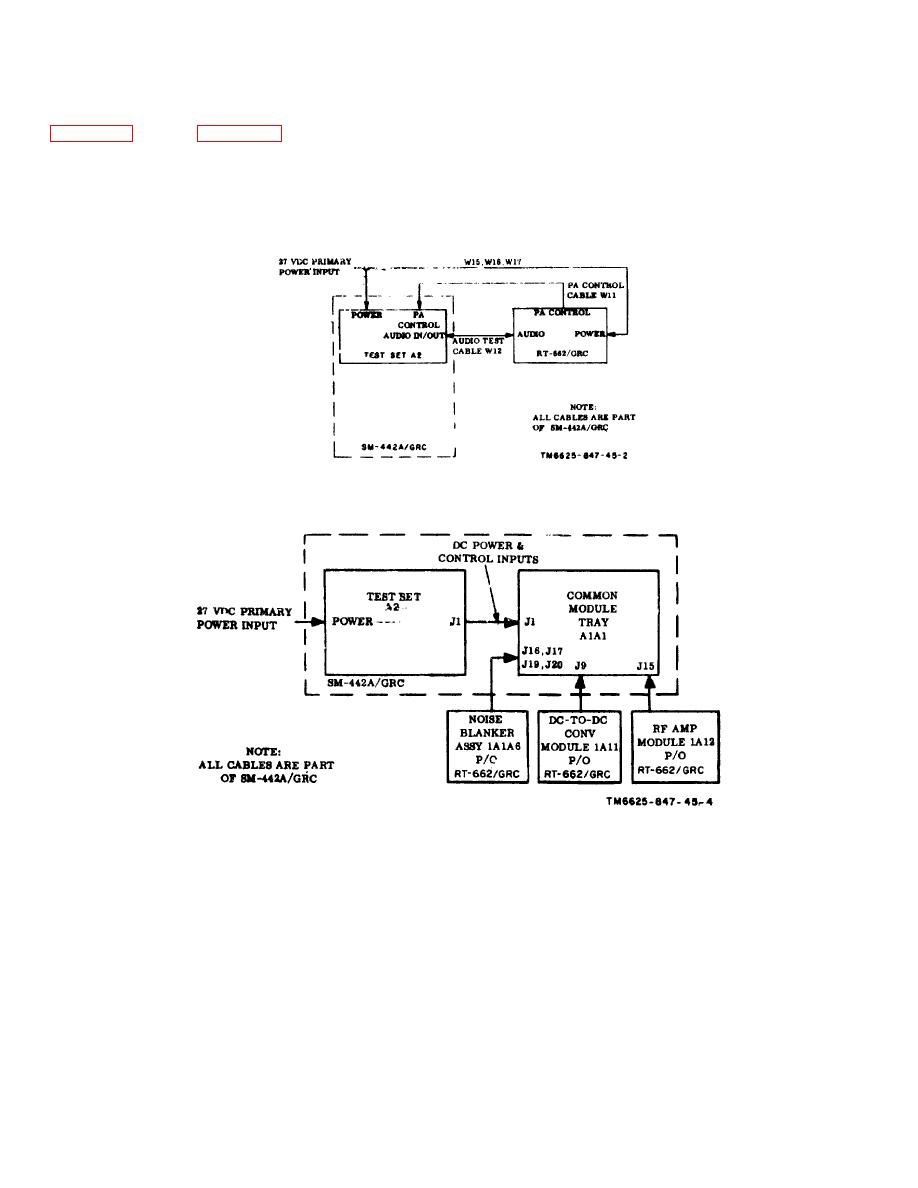
Figure 1-3. RT-662/GRC unit system testing, block diagram.
Figure 1-4. Common module tray A1A1, module-testing, block diagram.
1-4


 Previous Page
