TM 11-6625-847-45
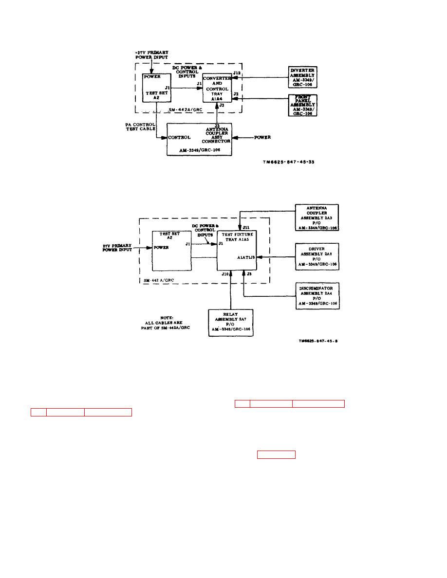
Figure 1-7. Converter and control tray A1A4, module testing, block diagram.
Figure 1-8. Driver, discriminator, and antenna coupler tray A1A5, module testing, block diagram.
Section III. FUNCTIONAL ANALYSIS
Note. Partial reference designators are used in
1-7. General
designators with test set reference designator A2, unless
otherwise specified.
each of the five test fixture trays of the SM-442A/GRC,
describing first the major components, purpose, and
operation of each and then the detailed circuits of
1-8. Test Set A2
electronic subassemblies or modules when necessary.
This is done, whenever possible, on a simplified
schematic or block diagram.
inputs, test points, and resistive loads supplied by the
test set. The +27-volt dc primary power is supplied
through the ON position
1-6


 Previous Page
