TM 11-6625-847-45
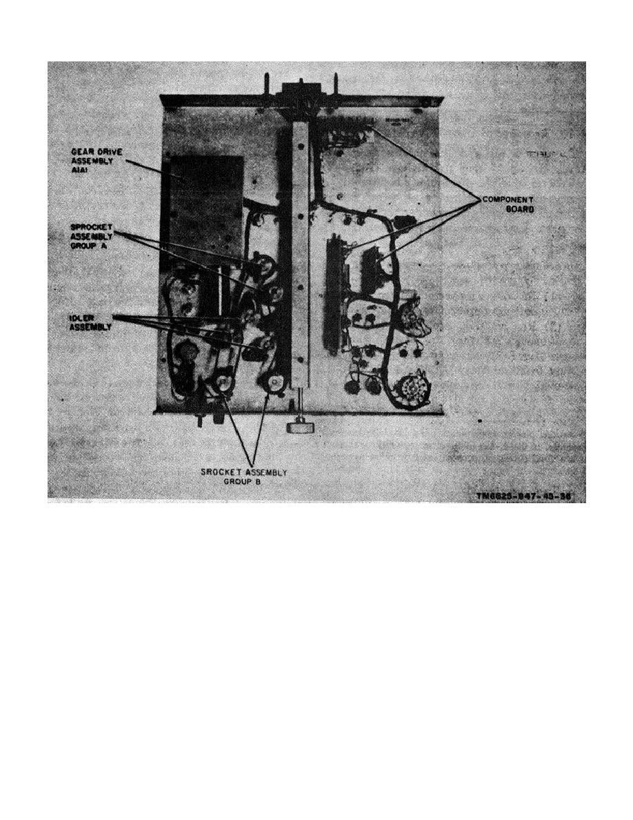
Figure 3-1. Common module tray A1A1, module and subassemblies locations.
the adapter bearing. Replace the retaining ring (7) on
(wiper contact on the rear of the switch wafer (15)).
the top of the spur gear shaft.
Rotate the wafer switch until an infinity indication is
owned on the ME-(*)/U.
g. Slide the spur gear (23) on the spur gear shaft (8),
(33) with the two screws (43) and two hex nuts (42).
d. Place the idler gear (3) on the idler gear shaft (2);
and tighten the hex setscrew (10) for snug fit. Slide the
drive gear (22) on the spur gear shaft (8), and tighten
lock it in place with the retaining ring (1).
the hex 5 screw (10) for snug fit. Align the drive gear
e. Press the idler gear shaft (2) into the bottom plate.
(22) with the idler gear (3); drive the pin (9) into the
f. Slip the switch wafer (15) into the switch shaft (24),
drive gear (22).
and secure it to the top plate (16) with the four hex nuts
h. Reassemble the channel motor (41) in the channel
(11), screws (12), flat -washers (13), and spacers (14).
motor mount (88), slip the worm
Using an ME-26(*)/U with the negative probe on pin 1 of
connector J1 and switch wafer (15) in position 29, place
the positive probe of the ME-26(*)/U on contact 29A
3-4


 Previous Page
