TM 11-6625-847-45
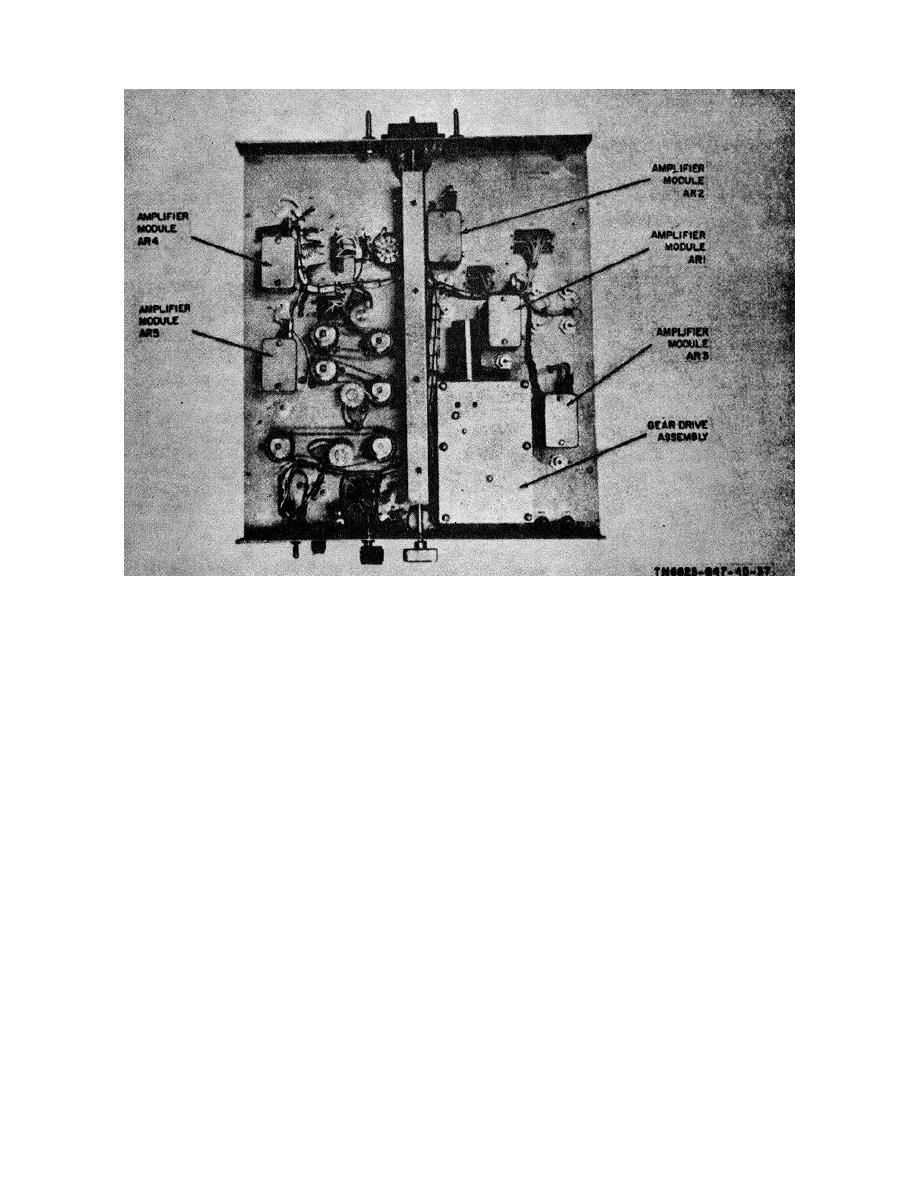
Figure 3-2. Synthesizer test to A1A3, module and subassemblies locations.
align. Secure the gear assemblies with the appropriate
gear (36) on the channel motor shaft, and tighten the
pins and hex setscrews.
hex setscrew (35) for snug fit. Fasten the channel motor
(41) to the channel motor mount (33) with the four
screws (38), lockwashers (39), and flat washers (40).
Note.
The gear drive assemblies are now
Attach the channel motor mount (33) to the top plate
electrically and mechanically aligned at 29 mc.
(16) with the two screws (32) and hex nuts (31).
i. Slide the switch gear (6) on the switch shaft
l. If wires were unsoldered from switch S1,
(24); lock the switch gear to the switch on the shaft with
resolder the wires to the power terminals as indicated by
the retaining ring (4).
the tags.
j. Secure the bottom plate with the six plate
m. Place the gear drive assembly in its proper
screws (17), six lockwashers (18), and six flat washers
position on the tray, and secure it with the four screws
(19).
previously removed.
k. Align the switch gear (6) with the idler gear (3),
n. On tray A1A3, place the coupler on the shaft
align the drive gear (22) with the idler gear (3), and align
with the pin towards the rear of tray A1A3, and secure it
the spur gear (23) with the worm gear (36). Align the
in position with the set screws.
notch on the coupler (26) so that the center line of the
notch and the center line of the screw hole (44) exactly
3-5


 Previous Page
