TM 11-6625-847-45
d. Tighten the hex setscrew (4). Using the pin (3),
connect the transformer assembly to the shaft.
e. Align the sprocket gear (2) with the pin hole in
the shaft (6). Drive the pin (1) through the sprocket gear
pin hole and through the shaft.
f. Position the turret assembly on the tray A1AS,
and secure it firmly in place with the four top panel
mounting screws (2, fig. 8-4).
g. Install the microswitch mounting screws (3)
securing it to the turret assembly top panel. Attach the
leads from the turret transformer assembly.
h. Attach the wires from the attenuator assembly
(1).
i. Slip the drive chain in place upon the sprocket
gear of the control shaft (fig. 3-7).
j. Rotate the idler sprocket gear inward toward the
drive chain making certain that it is in its original
position. Tighten the hex nuts.
3-16. Removal of Pulse Generator Subassembly
To remove the pulse generator subassembly from the
test set, refer to figure 3-10 and proceed as follows:
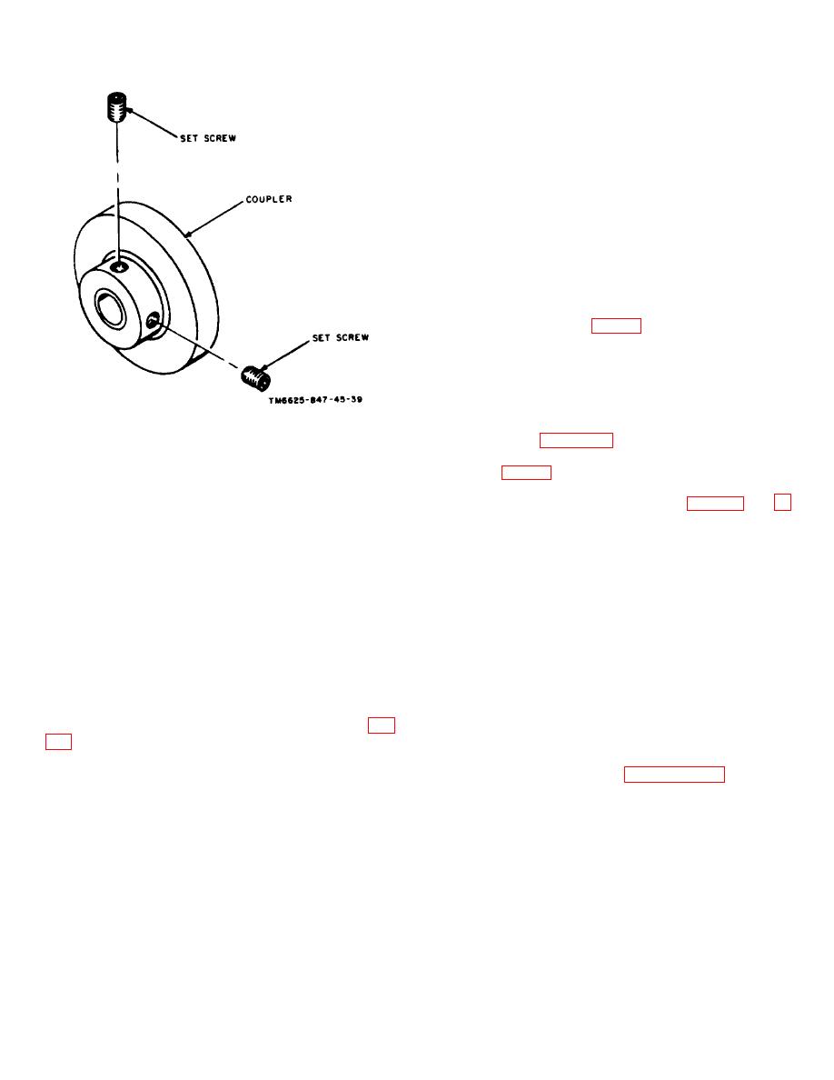
Figure 3-4. Common module tray A1A1, gear drive
assembly coupe.
14 on A1 (fig. 6-4).
b. Loosen the setscrew securing each of the two
b. Drive the pin (3) from the transformer assembly
WIDTH control knobs on the front pane (fig. 3-11 and 3-
with a drift punch. Loosen the hex setscrew (4) on the
12). Remove the knobs from the panel. Loosen the
transformer assembly.
setscrew securing each of the two AMPLITUDE control
c. Remove the turret assembly shaft top mounting
knobs on the front panel; remove the knobs from the
screw (5), and withdraw the shaft (6) from the
panel.
transformer assembly and the sprocket gear through the
c. Remove the two front panel screws which secure the
turret frame.
pulse generator assembly to the front panel. Remove
d. Slide the transformer assembly (7) sideways
the pulse generator assembly from the test set.
from the turret frame assembly.
e. Remove the seven screws (8) from the
3-17. Disassembly of Pulse Generator Assembly
transformer assembly top plate (9), and remove the top
To disassemble the pulse generator assembly after
plate. Remove the three transformer sections (10).
removal from the test set, remove the four screws and
four spacers which secure the pulse generator
3-15. Reassembly of Turret Transformer Assembly
subassembly to the generator plate.
Note.
To
remove
electrical
secure it with the seven screws (8).
components,
use
conventional
techniques. Refer to paragraph 3-1.
b. Slide the transformer assembly (7) sideways
toward the turret frame assembly.
c. Slide the turret assembly shaft (6) through the
turret frame, and slide the sprocket gear (2) and
transformer assembly (7) on the shaft.
3-7


 Previous Page
