TM 11-6625-847-45
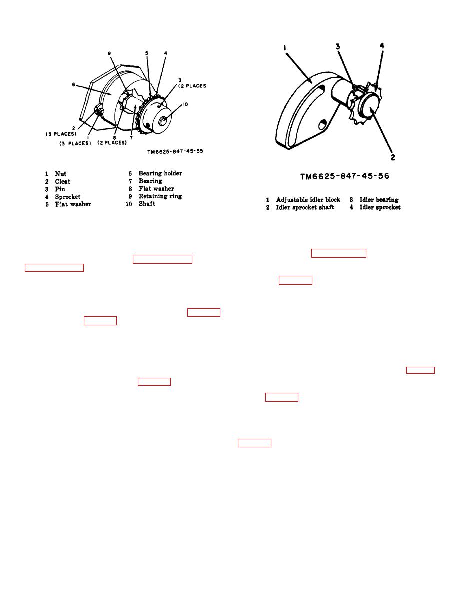
Figure 3-18. Sprocket assembly group B.
Figure 3-19. Idler assembly.
3-48. Replacement of Idler Assembly, Tray A1A3
(4), and remove the amplifier board from the case (7).
Note.
To remove parts, use convention A1
To remove, disassemble, and reassemble any of the
techniques. Refer to paragraph 3-1.
three idler assemblies, refer to paragraphs 3-34 through
3-51. Reassembly of Amplifier Modules AR1 through
AR5 (fig. 3-21)
3-49. Removal of Amplifier Modules AR1 through
ARS, Tray A1A3
To reassemble any of the five amplifier modules,
proceed as in a through c below.
To remove any of the five amplifier modules (fig. 3-21)
a. Place the amplifier board (4) in the case (7), and
from tray A1A3 (fig. 3-22), detach and tag the three leads
secure it firmly in position using the three screws (5) and
attached to connectors J1, J2, and J3 and detach the two
three washers (6). Connect the six leads to the amplifier
leads connected to terminals E1 and E2. Remove two
board.
nuts and four washers, and lift the amplifier module from
b. Position the cover (3)-on the amplifier module,
the tray A1A3.
and install the two screws (1) and two washers (2).
3-50. Disassembly of Amplifier Modules AR1
22), and install the two nuts and four washers. Attach
through AR5, Tray A1A3 (fig. 3-21)
connectors J1, J2, and J8, and connect the leads to E1
and E2 (fig. 3-21).
To disassemble any of the five amplifier modules,
proceed as in a through c below.
3-52.
Removal of Terminal Boards, Tray A1A4
a. Remove the two screws (1) and two flat washers
(2), and remove the cover (3).
To remove the two terminal boards from tray A1A4
b. Detach and tag the six leads connected to the
amplifier board (4).
Remove the nuts and washers securing the board to the
c. Remove the three screws (5) and three flat
tray A1A4.
washers (6) securing the amplifier board
3-22


 Previous Page
