TM 11-6625-847-45
3-40.
Removal of Terminal Board, Tray A1A2
To remove the terminal board from tray A1A2, (fig. 3-
20), remove the two nuts and four washers securing the
assembly to tray A1A2.
3-41. Disassembly of Terminal Board, Tray A1A2
To remove parts from the terminal board use
conventional replacement techniques.
Refer to
3-42. Reassembly of Terminal Board, Tray A1A2
Reassemble the terminal board on tray A1A2 (fig. 3-
20), using the four washers and two nuts.
3-40. Removal of IF Amplifier Subassembly A2,
Tray A1A2
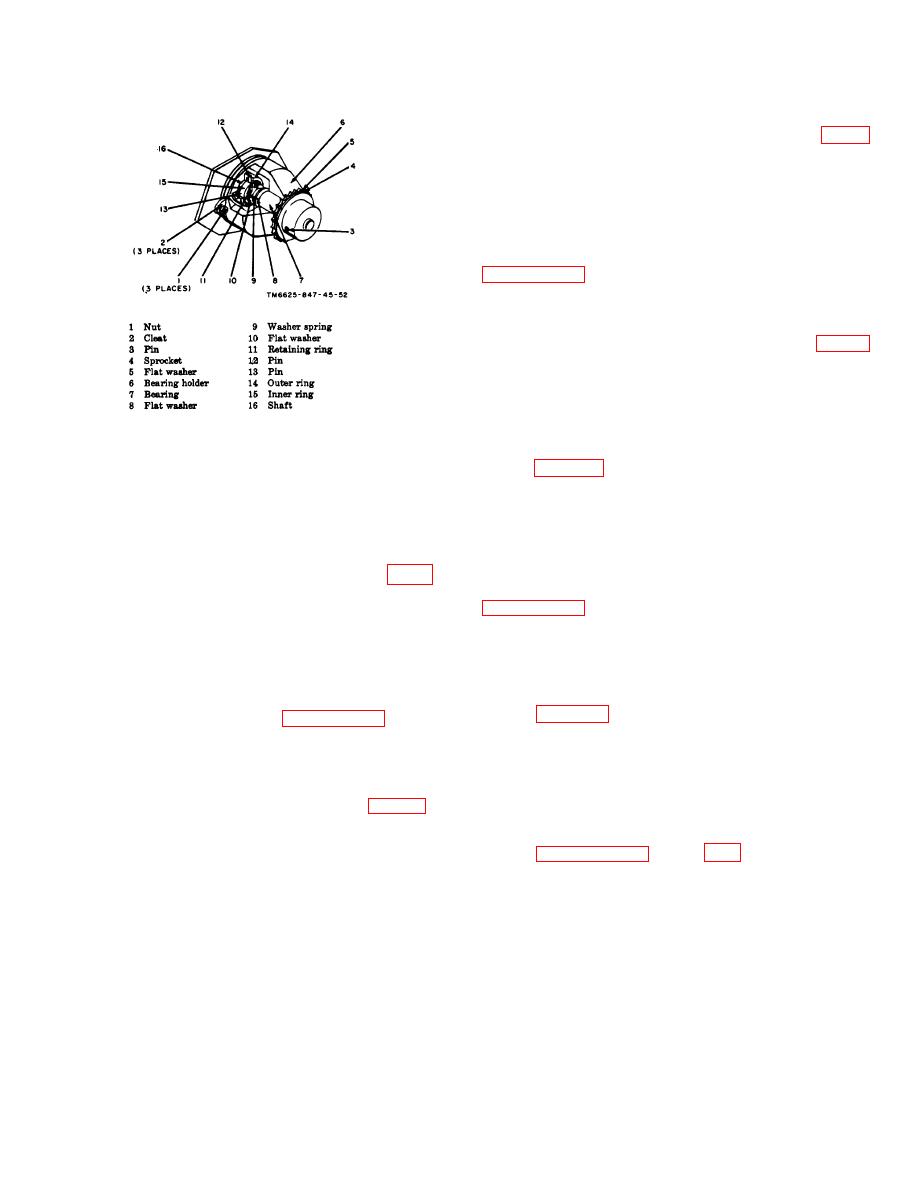
Figure 3-16. Sprocket assembly group A.
To remove IF amplifier subassembly A2 from tray
A1A2 (fig. 3-20), remove the four screws, four plain
c. Place the idler assembly in its proper position on
washers, and four lockwashers.
tray A1A1, and install the two nuts and two washers to
secure it firmly in place.
3-44. Disassembly of IF Amplifier Subassembly
A2, Tray A1A2
3-37. Removal of Component Boards, Tray A1A1
To remove parts from IF amplifier subassembly A2,
To remove any of the three component boards (fig. 3-
use conventional replacement techniques. Refer to
1), detach and tag all leads connected to the component
board and remove the two nuts and four washers.
3-45. Reassembly of IF Amplifier Subassembly A2,
3-38. Disassembly of Component Boards, Tray
Tray A1A2
A1A1
Reassemble IF amplifier subassembly A2 on tray
To remove parts from a component board, use
A1A2 (fig. 3-20), using the four screws, four plain
conventional techniques. Refer to paragraph 3-1.
washers, and four lockwashers.
3-39. Reassembly of Component Boards, Tray
3-46. Replacement of Sprocket Assembly Groups
A1A1
A, Tray A1A3
Secure the component board to tray A1A1 (fig. 3-1),
To remove, disassemble, and reassemble any of the
with the two nuts and four washers. Connect the leads.
three A-type sprocket assembly groups of tray A1A3,
refer to paragraphs 3-28 through 3-30.
3-19


 Previous Page
