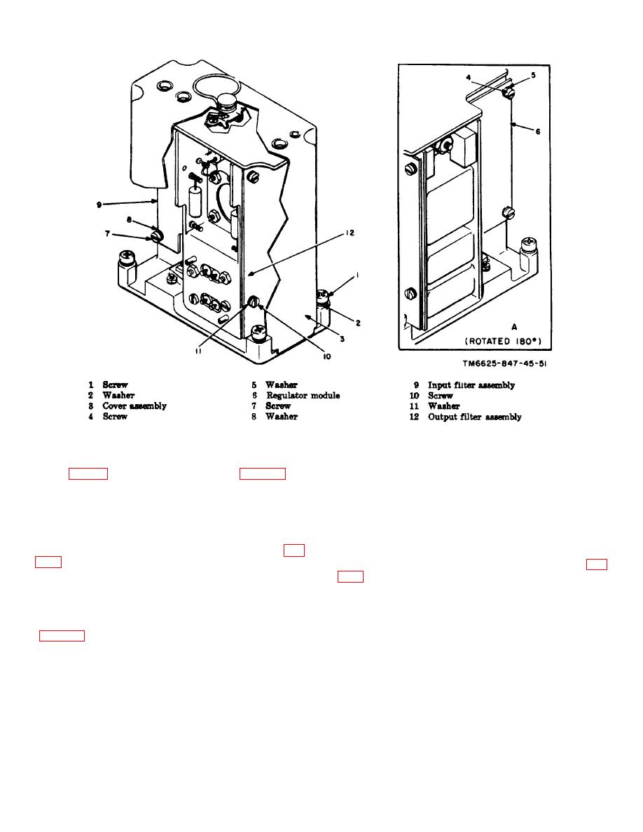
Figure 3-15. Dc to dc- converter and regulator module A3.
a. Remove the idler sprocket shaft (2) which is
e. Place the assembly in its proper position on tray
pressed into the adjustable idler block (1).
A1A1 (fig. 3-1). Install the three cleats (2, fig. 3-18) on
the three studs, and secure the sprocket assembly group
b. Remove the idler bearing (3) and idler sprocket
firmly in position with the three nuts (1).
(4) from the shaft. Remove the press fitted idler bearing
(3) from the idler sprocket.
3-34. Removal of Idler Assembly, Tray A1A1
3-36. Reassembly of Idler Assembly, Tray A1A1
To remove any one of the three idler assemblies (fig.
To reassemble any of the three idler assemblies (fig.
secure the adjustable idler block (1) to tray A1A1.
a. Press the idler bearing (3) into the idler sprocket
3-35. Disassembly of Idler Assembly, Tray A1A1
(4).
b. Slide the idler bearing (3) and idler( sprocket (4)
To disassembly any one of the three idler assemblies
on the idler sprocket shaft (2) and press the shaft into
the adjustable idler block (1)
3-18


 Previous Page
