TM 43-6625-916-12
RADAR TEST SET
THEORY OF OPERATION
TEST SET PRINCIPLES OF OPERATION
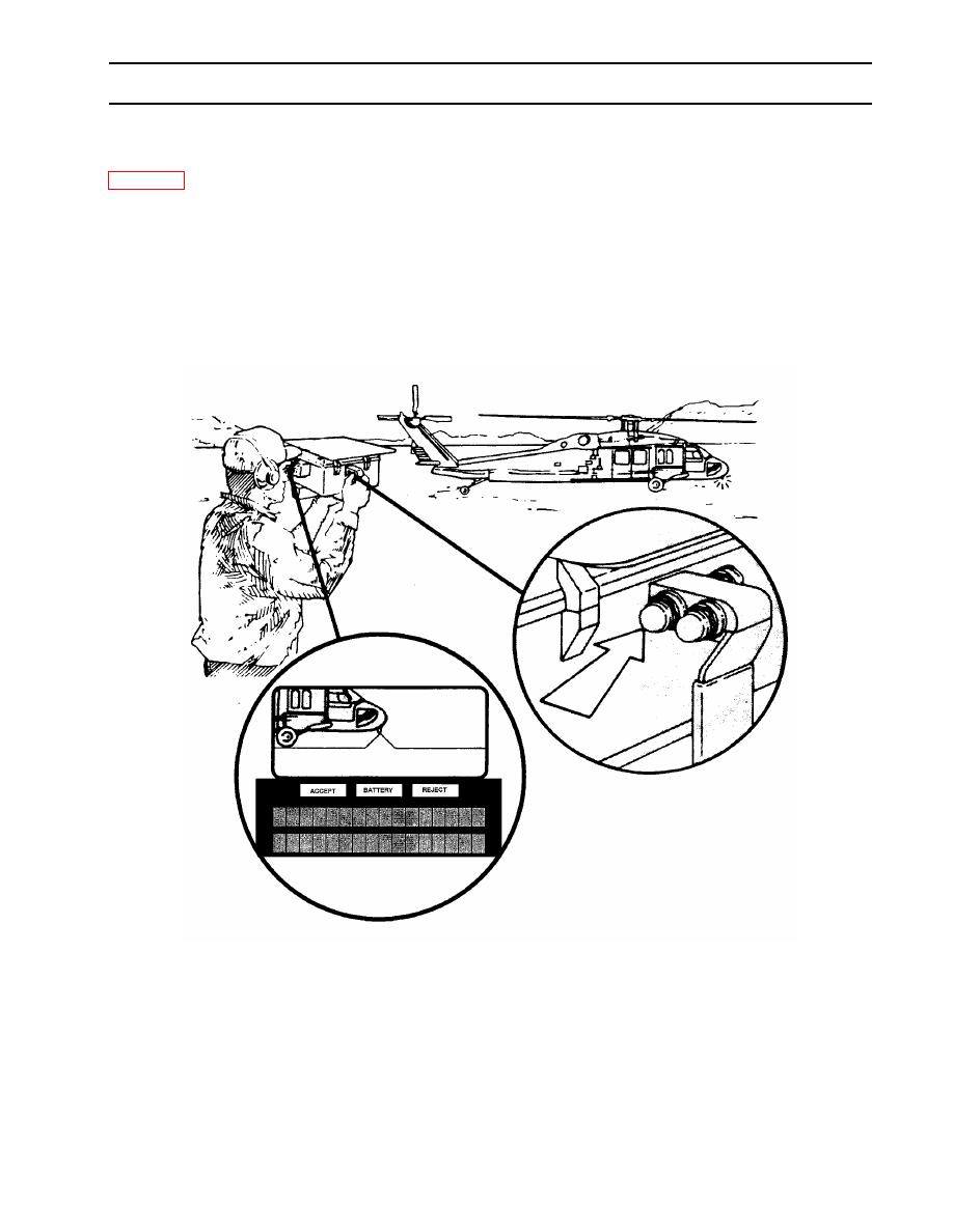
Figure 3-1 illustrates the general operation of the Test Set. Operator control of all test functions is provided via
three buttons (S1, S2, and S3) located on the unit handgrip. Once power is applied to the unit and the Built-In
Test (BIT) is complete, transponder or interrogator testing may begin. Testing is performed while aiming the
Test Set at the UUT's (Unit Under Test) antenna through the unit viewfinder (radiated test mode) or via RF
test cable (direct connect test mode). Prompts are displayed to the user to assist in operation of the Test Set
and test results are displayed to verify transponder/interrogator status and to assist in diagnosing system
performance abnormalities. An alphanumeric display is located below the viewfinder inside the Test Set
enabling the operator to continue aiming the Test Set while reading prompts and test results. Test results for
as many as 100 tests may be stored if desired and downloaded to a PC via RS-232 port (the port is accessed
by way of the RS-232 connector located on the KIT/KIR interface cable).
When power is initially applied to the Test Set, i.e. a battery stick is installed or external dc power is applied
with no batteries installed, the unit performs a BIT test of approximately 5 seconds duration. The results of
the self test are displayed once completed. After power is applied, the unit has two operating states. They
are active mode and standby mode. The Test Set transitions from active to standby mode after approximately
one minute has passed with no operator input (no Test Set buttons pushed). Standby mode is a battery-
power conservation state. Power is removed from the display and other non-essential circuits while in this


 Previous Page
