TM 11-5840-281-12-1
4-23.
INTERCONNECTING CABLES. (CONT)
INTERCONNECTING CABLE INSTALLATION
Referring to FO-1, interconnecting cable diagram, install interconnecting cables as described in the following steps.
Radar Site
305NE162
1.
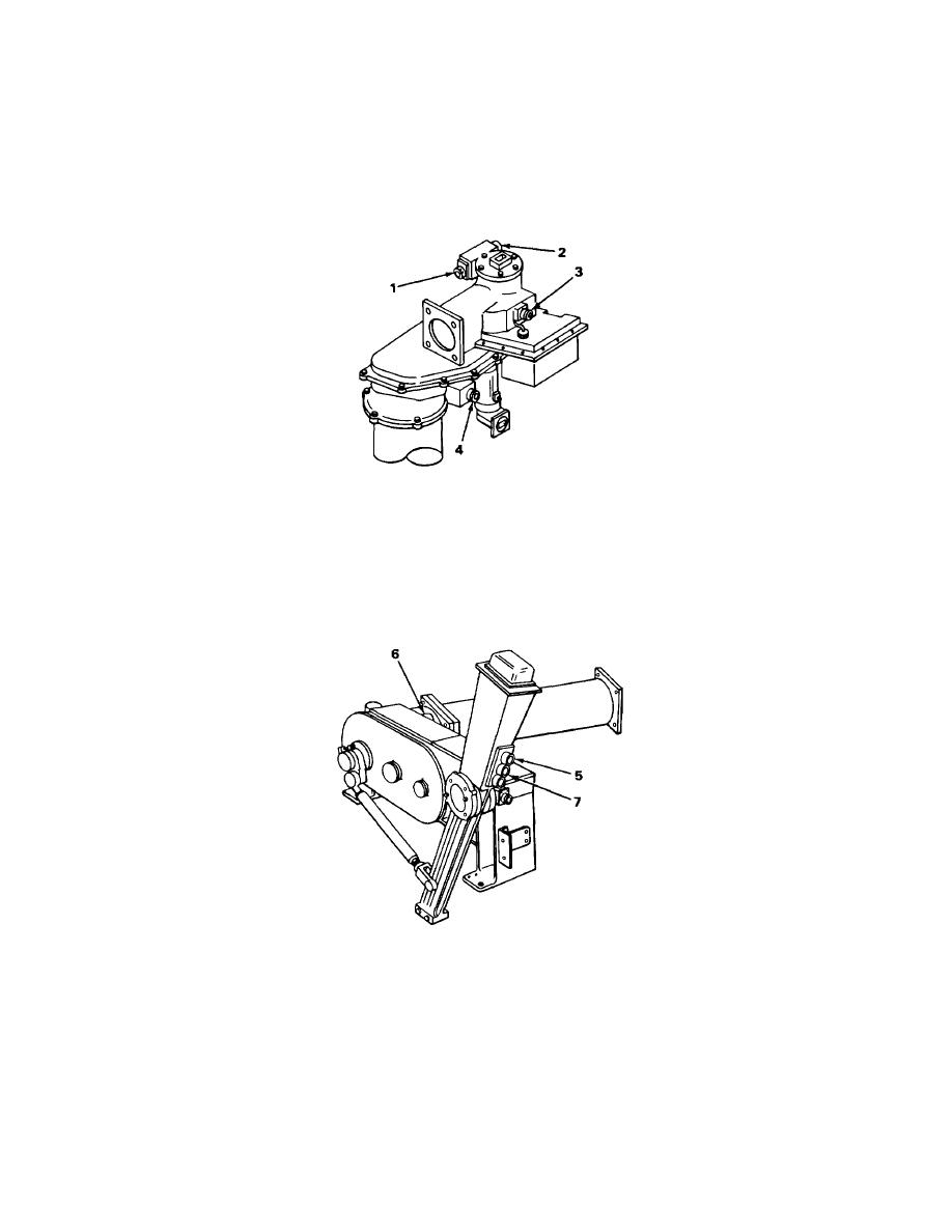
Connect following cables to azimuth antenna drive as indicated:
a.
Connect P1004 of cable W9301 (hardwired to azimuth horn and polarizer) to J1004 (1).
b.
Connect P1002 of cable W9101 (hardwired to azimuth servo actuator) to J1002 (2).
c.
Connect P1001 of cable W3501 to J1001 (3).
d.
Connect P1003 of cable W3502 to J1003 (4).
305NE163
2.
Connect following cables to elevation antenna drive as indicated:
a.
Connect P504 of cable W9101 (hardwired to elevation servo actuator) to J504 (5).
b.
Connect P505 of W9201 (hardwired to elevation horn and polarizer) to J505 (6).
c.
Connect P501 of cable W3503 to J501 (7).
4-48


 Previous Page
