TM 11-5840-281-12-1
4-25.
GROUND ANGLE DETERMINATION.
NOTE
If more than one runway approach is being used, determine and record the ground angle for each td
point in accordance with steps 1 through 10.
If radar site is at a higher elevation than td point, resulting ground angle is negative and must not exceed
- 1 degree.
It is possible that ground angle may have already been determined. See Site and Shelter Requirements, Equipment
Siting Procedures (para 4-5). Even if this is true, ground angle must be checked using siting scope and clinometer,
which are supplied as part of radar set. Siting scope, when used in conjunction with azimuth antenna scan protractor,
serves as a theodolite or transit. Clinometer serves as an elevation scan protractor.
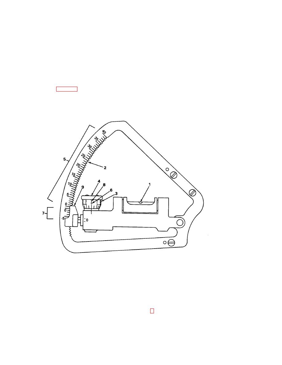
USING THE CLINOMETER
305NE094
The clinometer pictured above uses a bubble level (1) to determine the vertical angle of the elevation antenna. The
degree scale (2) is adjustable between - 5 and 40 degrees in increments of 1 degree. The vernier scale (3) on the
adjustment knob (4) has a 1-degree range, calibrated in 0.05-degree increments. The black degree markings, (5) on the
degree scale and (6) on the vernier scale, are read as positive angles. The red degree markings, (7) on the degree scale
and (8) on the vernier scale, are read as negative angles. For example, an angle of + 3.2 degrees would position the
pointer (9) at the third notch above the black zero on the degree scale and at 0.2 on the black degree markings of the
vernier scale. For an angle of - 3.2 degrees, the pointer would be three notches below the red zero on the degree scale
and at 0.2 on the red degree vernier markings of the vernier scale.
4-53


 Previous Page
