TM 11-5840-281-12-1
4-28. CIRCUIT ALINEMENT. (CONT)
ANGLE
SINE
ANGLE
SINE
6.0
0.10453
8.1
0.14090
6.1
0.10626
8.2
0.14263
6.2
0.10800
8.3
0.14436
6.3
0.10973
8.4
0.14608
6.4
0.11147
8.5
0.14781
6.5
0.11320
8.6
0.14954
6.6
0.11494
8.7
0.15126
6.7
0.11667
8.8
0.15299
6.8
0.11840
8.9
0.15471
6.9
0.12014
9.0
0.15643
7.0
0.12187
9.1
0.15816
7.1
0.12360
9.2
0.15988
7.2
0.12533
9.3
0.16160
7.3
0.12706
9.4
0.16333
7.4
0.12880
9.5
0.16505
7.5
0.13053
9.6
0.16677
7.6
0.13226
9.7
0.16849
7.7
0.13399
9.8
0.17021
7.8
0.13572
9.9
0.17198
7.9
0.13744
10.0
0.17360
8.0
0.13917
3.
Subtract elevation 5-mile intercept angle (A) from glidepath angle (C) to find elevation alinement angle (B).
Record this angle for future use.
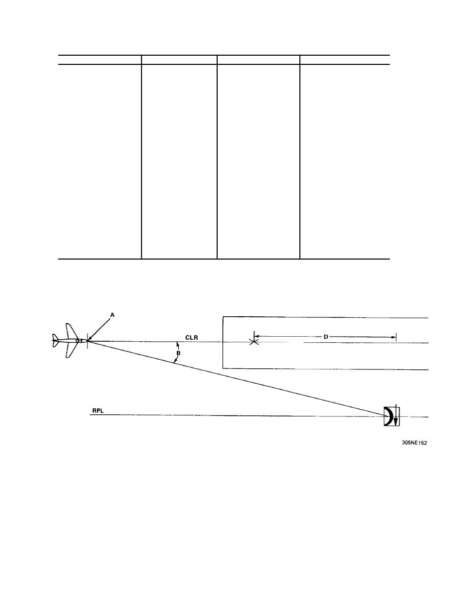
DETERMINING ANGLE VOLTS SETTING FOR AZIMUTH OFFSET ANGLE
Because radar set is offset from center of runway, an angle exists between radar set group and a point (A) 5 miles from
td on clr (aircraft courseline). This is azimuth offset angle (B). This angle is used during azimuth cursor alinement and is
represented by a specific setting of ANGLE VOLTS control on pulse generator. Determine pulse generator ANGLE
VOLTS control setting for each runway approach by performing the following steps.
4-91


 Previous Page
