TM 11-5840-281-12-1
4-28. CIRCUIT ALINEMENT. (CONT)
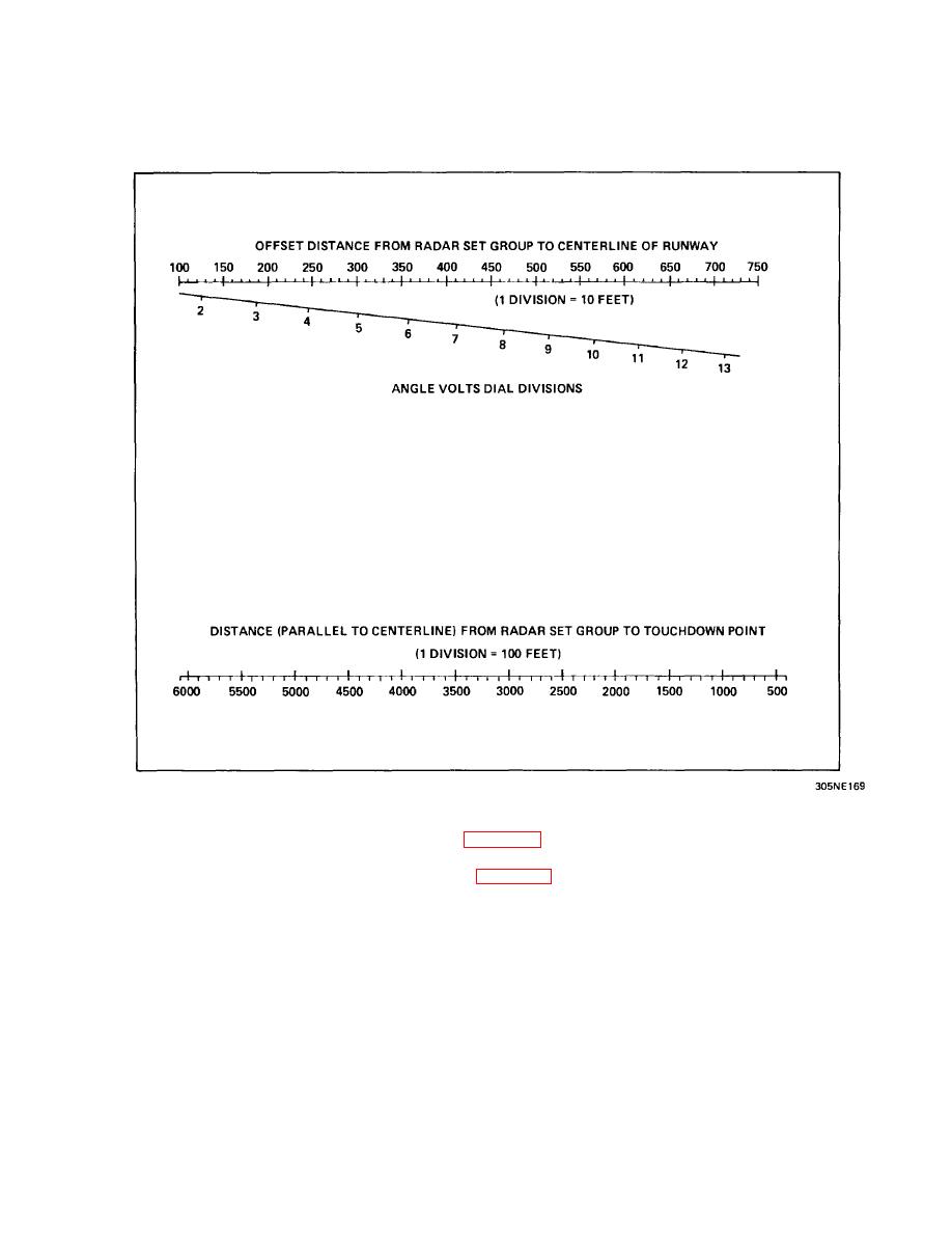
DETERMINING ANGLE VOLTS SETTING FOR AZIMUTH OFFSET ANGLE (CONT)
1.
On top scale of azimuth nomograph above, locate and mark the point that represents radar offset from clr
distance determined in Siting of Target Simulators (para 4-26).
2.
On bottom scale of azimuth nomograph, locate and mark the point that represents distance from radar set group
to td point determined in Siting of Target Simulators (para 4-26).
3.
Using straightedge, connect points marked in steps 1 and 2. Record the value at point of intercept on ANGLE
VOLTS DIAL DIVISIONS line. This is the setting representing azimuth offset angle.
CURSOR ALINEMENT
Up to two sets of cursors can be alined for each control-indicator, depending on the number of runways being given gca
service. If only one runway is receiving gca service, aline one set of cursors on both master and slave control-indicators.
If two runways are being given gca service, aline two sets of cursors to their respective runways on both master and
slave control-indicators. Use the following cursor alinement procedures for each set of cursors to be alined.
4-92


 Previous Page
