TM 11-5840-281-35/1
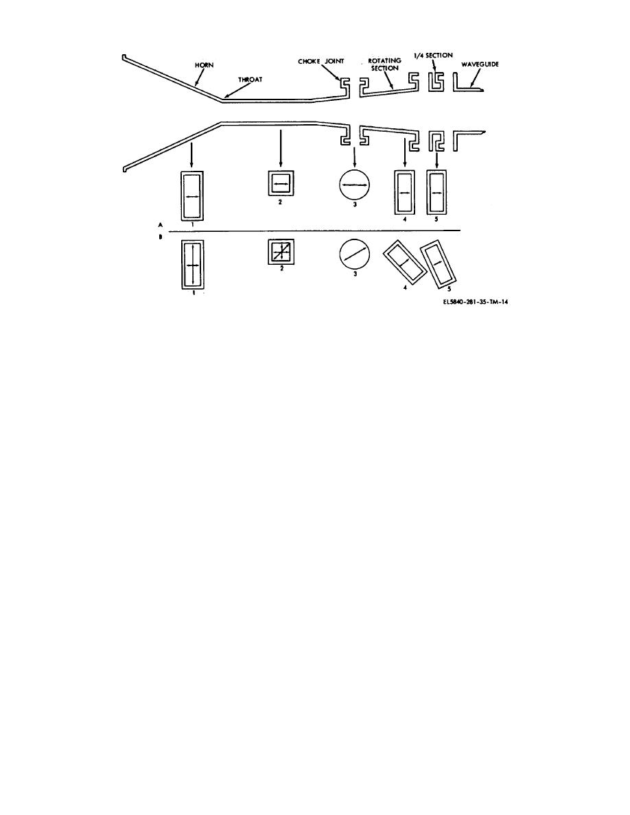
Figure 2-14. Dual function polarizer assembly
ceiver section is to produce detected video signal from
ously switches +28 volts to either the forward or reverse
the reflected signal delivered by the rf section. The timing
winding of each polarizer actuator motor, B501 and
of the video signals indicates the range of the radar
B1001. Limit switches S501 and S502 in the azimuth
target that reflected the signal. The output detected
polarizer actuator assembly, and limit switches S1001
video signal is sent to the indicator section. The receiver
and S1004 in the elevation polarizer actuator assembly,
section is comprised of a superheterodyne receiver
control the positioning of the rotating waveguide sections
which operates as both a single- and dual channel
integral to the respective feedhorn assemblies.
f. Antenna Reflectors. The reflectors for azimuth
receiver. The receiver section consists of tr tubes, a
local oscillator, a mixer assembly, two i-f preamplifiers, a
Antenna AS-1292/TPN-8 and elevation Antenna AS-
sensitivity time control (stc), an i-f amplifier, a log i-f
1291/TPN-8 are molded structures with integral
amplifier, an i-f delay line, and a video amplifier. Dual-
mounting features for the feedhorn assembly and
channel operation is required for the separate sum and
attachment to Antenna Pedestal AB-738/TPN-8.
difference signals that are developed in the rf section.
(1) The azimuth antenna is composed of a 8+ by
The two channels are designated as the sum channel
6-foot distorted parabolic reflector of honeycomb
and the difference channel.
construction. The distorted parabolic reflect or provides a
(1) The sum and difference signals enter the
cosecant-squared coverage pattern in the vertical plane
receiver section at the mixer assembly, which is common
and a horizontal beamwidth of approximately 1.2
to both channels. Following the mixer assembly, the two
degrees.
channels are separated. The sum channel continues
(2) The monopulse elevation antenna is
through an i-f preamplifier (Intermediate-Frequency
composed of a 2 by 8-foot parabolic reflector. The
Amplifier AM-3337/ TPN-8), a i-f delay line, an i-f
parabolic reflector provides a vertical beamwidth of
amplifier (Inter mediate-Frequency Amplifier
approximately 1.1 degrees and a cosecanted beam in
AM3339/TPN-8), and a video amplifier. After the mixer
the horizontal plane.
assembly, the difference channel continues through the
2-4. Receiver Section Description
second i-f preamplifier (Intermediate-Frequency Amplifier
(fig. 7-7)
AM-337/TPN-8), a log i-f amplifier (Intermediate-
a. General. The primary function of the re-
Frequency Amplifier AM-338/
2-15


 Previous Page
