TM 11-5840-281-35/1
from the narrow end, where the impedance matches the
vertical beamwidth of the elevation antenna by adjusting
waveguide, to the wide end, where the impedance of the
the gain of the difference channel of the receiver
feedhorn matches the impedance of the space between
section. Consider the following sequence: (a) As the
the feedhorn and reflector. The flared shape of the horn
elevation antenna scans up, the patterns approach an
serves to change the internal impedance smoothly and
aircraft target.
(b) As the upper edge of the sum pattern
prevent losses due to mismatches causing rf reflections
back down the waveguide. Antenna AS-1292/ TPN-8
illuminates the target, the center of the upper difference
uses a conventional single-channel wave- guide and
pattern is on the target.
(c) The received energy is directed into the
feedhorn assembly. Antenna AS-1291/ TPN-8 uses a
dual-channel waveguide and feed- horn assembly (sum
difference channel and the output of the difference
and difference channels) to provide increased angular
channel reduces the sum channel gain nearly to zero.
resolution.
(d) As the center of the sum pattern reaches the
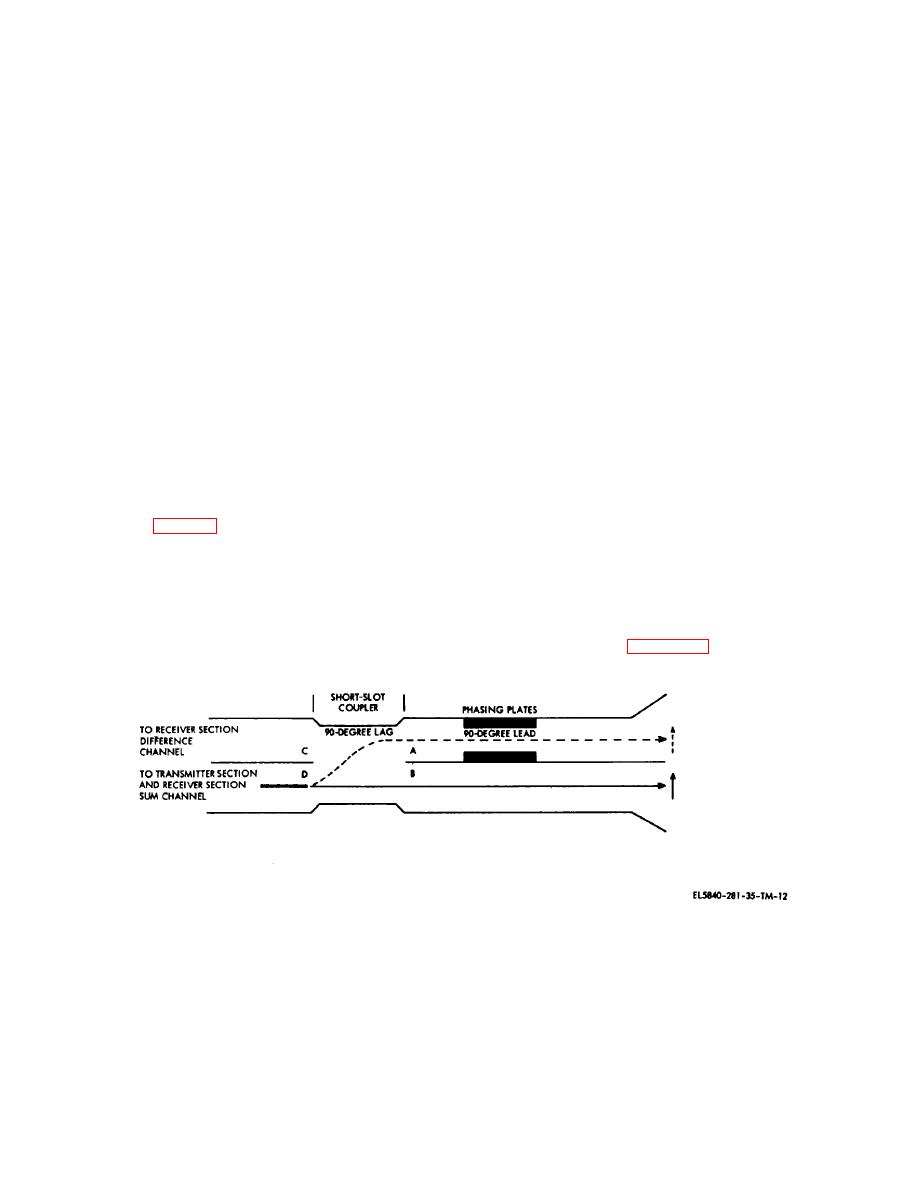
(1) Rf energy from the transmitter section enters
target, no energy is received by the difference channel.
the elevation sum channel through the ferrite switch, and
The gain of the sum channel returns to normal and the
is split equally in the feedhorn short-slot coupler. The
blip is displayed.
energy that passes through the coupler to line A (fig. 2-
(e) As the lower edge of the sum pattern reaches
12) lags the energy in line B by 90 degrees. Phasing
the target, the lower difference pattern is centered on
plates in line A produce a phase-lead of 90 degrees with
the target and again the sum channel gain is reduced
respect to line B. With the 90-degree lag through the
nearly to zero.
short- slot coupler and the 90-degree lead through the
(f) The only signals that are displayed are those
phasing plates, the signals in line A and line B are in-
received when the sum channel is most nearly centered
phase at the feedhorns. Two side-by-side lobes of
on the target. The apparent vertical beamwidth is
energy, one each from lines A and B, are thereby
operator-adjustable to less than that which could be
radiated into space.
realized by conventional means (to about 0.4 degree).
(2) The algebraic sum of the two lobes is plotted
(e) Polarization. Choice of linear or circular
as a solid line (fig. 2-13). The algebraic difference is
polarization for Radar Set AN/TPN-18 is made possible
plotted as a dashed line on the same figure. The
by the use of integral polarizers. Changing between
phasing in the feedhorn is so arranged that when the
linear and circular polarization in this device is
energy is being received, the position of any target with
accomplished by rotating the feed- horn-associated
respect to the center of the sum pattern (0 degree) will
waveguide 45 degrees at the point where it feeds the
determine the amount of energy which will be coupled to
horn.
the sum channel and/or the difference channel
(1) The general configuration of the integral
waveguide.
polarizer is shown in figure 2-14. Cross-sections
(3) The operator can control the apparent
Figure 2-12. Antenna AS-1291/TPN-8 feedhorn.
2-13


 Previous Page
