TM 11-5840-281-35/1
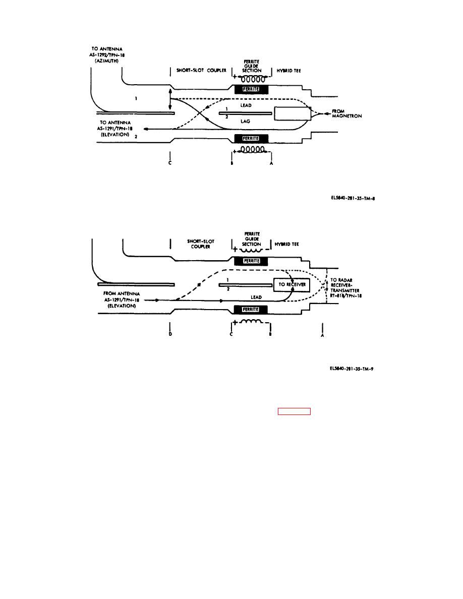
Figure 2-8. Ferrite switch transmit path.
Figure 2-9. Ferrite switch receive path.
is now 180 degrees out-of-phase in the hybrid tee and
current by two thermistors packaged in the ferrite
will vectorially cancel at point A. If the energy field of line
assembly (fig. 2-10). Resistor R125 shun the
1 is from top-to-bottom and the energy field of line 2 is
thermistors to give an optimum amount of thermistor
from bottom-to-top, the fields will be 180 degrees out-of-
compensation. Normal electromagnet current is between
phase and the energy will fold into the receiver
90 and 440 ma. (The exact required current is marked
waveguide in- phase and enter the receiver section.
on the individual ferrite switch section.) The dc current
(4) Switching action between the antennas is
source is a phase, half-wave rectifier connected to the
accomplished by reversing the direction of current flow
primary power source. The current is limited by
through the coils of the electromagnet.
resistors R122 ,R12, and R124. Resistor R128 variable
here are four windings in the electromagnet of the ferrite
to permit adjustment for the correct amount of current.
switch section, connected in series parallel with a
Electromagnet current be monitored with a multimeter by
combined resistance of 150 ohms. This section is
measuring the voltage drop across resistor R122
subjected to severe temperature changes and
between test- points TP1 and TP104. Relay K4016 in
compensation made in the electromagnet
Remote
2-10


 Previous Page
