TM 11-5840-281-35/1
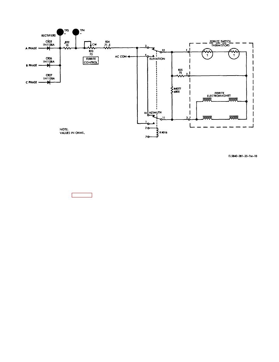
Figure 2-10. Ferrite switch control circuit, simplified schematic.
Switching Control C-6989/TPN-18 reverses the current in
used to adjust current for the attenuator in the elevation
the ferrite switch windings to achieve the switching of rf
rf line. These controls are switched in the proper
between the antennas.
sequence by the contacts of az-el switching relay K4016.
Simultaneously, relay K4016 switches the current
regulator to the proper attenuator. When attenuation is
from nearby transmitters may enter the idle antenna,
off, the electromagnet current is limited by resistors R129
despite the action of the ferrite switch, and cause false
and R130 in Receiver-Transmitter RT-818/ TPN-18
video signals. To reduce this possibility, ferrite
Resistors R129 and R130 are then in series with their
attenuators located in Radar Receiver-Transmitter RT-
respective coils. When attenuator is on, the current is
818/TPN-18 are inserted in each antenna line.
shunted around one of these series resistors to the
(1) The attenuators are switched in or out by the
attenuator in the idle antenna line. The current can be
amount of current flowing in or out through the
monitored with a multimeter between testpoints TP4005
electromagnets around the ferrite strips. The attenuators
and TP4006 to measure the voltage drop across resistor
provide approximately 40-db round trip attenuation when
R4073. Resistor R4073 and testpoints TP400i and
a current of 500 to 700 ma flows through their windings.
TP4006 are in Remote Switching Control C-6989/TPN-
The attenuation is reduced to a minimum (about 1 db
18.
round trip) when a dc current of approximately 100 ma
(2) Current through resistor R120 and tran-
flows through the coil. The amount of current is critical,
sistors Q4015 and Q4016 is shunted around series
and a current-regulating circuit is provided along with the
resistors R121, R127, and R128. The combined
switching circuit in Remote Switching Control C-
resistance of transistors Q4015 and Q4016 is con- trolled
6989/TPN-18. Optimum current through the
by the current through their base circuits.
electromagnet coils is adjusted by controls in Remote
If the base voltage of transistor Q4015 is fixed,
Switching Control C-6989/TPN-18. AZ ATTEN control
transistor Q4015 and resistor R120 become a constant
R4063 b used to adjust current for the attenuator in the
current device, since any change in collector (and
azimuth rf line, and EL ATTEN control R4064 is
emitter) current results in a degenerative
2-11


 Previous Page
