TM 11-5840-281-35/1
(27) Attach shaft coupling (43) to gearshaft (52)
(33) Attach switch actuator (29) and switch (30) to
using setscrews (39).
cover plate (32) using screws (27 and 28).
(28) Insert variable resistor (42) shaft in shaft
(34) Adjust cam (49) to actuate switch (30) just
coupling (43) and attach variable resistor to mounting
before ram tube assembly (73) is retracted fully.
bracket (47) using nut (40) and lockwasher (41).
(35) Adjust cam (45) to actuate switch (85) just
(29) Secure shaft coupling (43) to shaft of variable
before ram tube assembly (78) is extended fully.
resistor (42) with setscrews (39).
(36) Install dc motor (26) to tube-gearbox (83)
(30) Attach cover plate (39) to tube-gearbox (83)
using four screws (25).
using screw (37).
(37) Attach rf filter (24) to actuator cover (12) using
(31) Attach switch actuator (35) and switch (86) to
two nuts (21), screws (22), and washers (23).
cover plate (38) using screws (33 and 84).
(32) Attach cover plate (32) to tube-gearbox (83)
using screw (31).
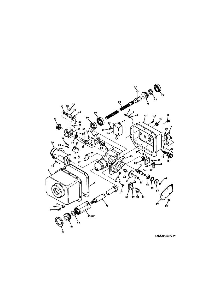
Figure 5-8. Antenna servo actuator, exploded view.
5-24


 Previous Page
