TM 11-5841-287-12
CHAPTER 2
OPERATING INSTRUCTIONS
Section I. OPERATOR'S CONTROLS AND INSTRUMENTS
2-1. Damage From Improper Settings
link control illuminates during normal
Observe the following warnings and cautions when
operation, attempt to correct the fault by
operating the data transmitting set.
cycling the POWER switch between STBY
WARNING
and OFF several times, allowing 30-
When the data transmitting set and radar
seconds between transitions. If a fault
set are operated on the ground (during
indication still remains, refer to paragraph
preflight, etc), be sure all personnel
maintain a minimum distance of three feet
from the antenna to prevent injuries from rf
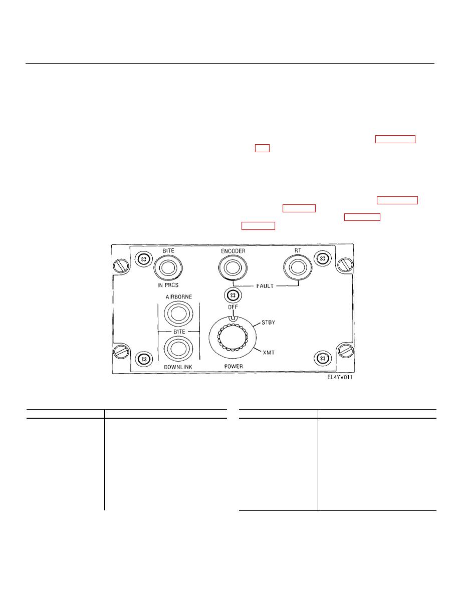
2-2. Operator's Controls and Indicators
All controls and indicators required for operation of the
data transmitting set are located in the data link control
CAUTION
and the uhf radio control. The controls and indicators of
Illumination of either the ENCODER FAULT
the data link control are shown in figure 2-1 and
or RT FAULT indicator during normal
described in table 2-1. The controls and indicators of the
operation indicates a possible power
uhf radio control are shown in figure 2-2 and described in
supply malfunction. If either the ENCODER
FAULT or RT FAULT indicator on the data
Figure 2-1. Data link control and indicators.
Table 2-1 Data Link Control Controls and Indicators
Table 2-1 Data Link Control Controls and Indicators-continued
Control or indicator
Function
Control or indicator
Function
Bite test
POWER switch
In OFF position, deenergizes data
BITE IN PR green CS
When on, indicates AIRBORNE
transmitting set
indicator
BITE or DOWNLINK
In STBY position, energizes uhf
test in process BITE
radio set and encoder (unit 2)
ENCODER FAULT
When on, indicates encoder (unit 2)
In XMT position, energizes
indicator (yellow)
or power supply malfunction
transmitter in uhf radio set
RT FAULT indicator
When on, indicates either a data
AIRBORNE BITE
When pressed, initiates data Link
(yellow)
synchronization or a low rf power
switch
control lamp test and AIRBORNE
malfunction in the uhf receiver
BITE test
DOWNLINK BITE
When pressed, initiates data link
test
control lamp test and DOWNLINK
2-1


 Previous Page
