
TM 11-5841-287-30
NOTE
The TEST red indicator lamp for the
switch selected will be illuminated while
the test is m progress
(8) Initiate a second test by repeating step
(7) above Verify that the green PASS indicator lamp on
the digital tester illuminates at the completion of the
second test
(9) Set the DISPLAY switch on the digital
tester to PROBE.
(10) Refer to figure 3-16 for test point
locations and connect the logic probe to each test point
listed below. While monitoring each test point, initiate a
test by pressing down on the digital tester TEST switch.
Verify that the correct corresponding transition
counts are displayed on the digital tester counter
Test Point
Count
U27-2
2918
U27-3
2918
U27-4
23535
(11) Connect the logic probe to each test
point listed below While monitoring each test point,
initiate a test by pressing down on the digital tester TEST
switch Verify that the logic probe tip is illuminated or off
during the test as shown below
Test Point
Probe Tip
U39-12
Illuminated
U39-13
Illuminated
U28-11
Illuminated
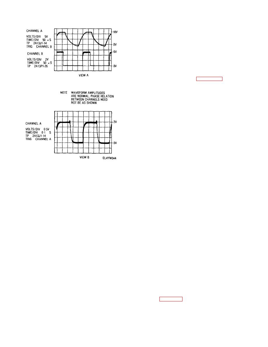
Figure 3-15. Power fault detector 2A13 waveforms
U28-9
Off
(12) Set the DISPLAY switch on the digital
ON/OFF switch to ON and the MODE SELECT switch to
tester to PASS/FAIL
MODULE TEST ENC Verify that the MODE/POWER
(13) Remove A14 program card no 1 from
MODULE TEST ON green indicator lamp is illuminated
the card reader slot
(14) Insert A14 program card no. 2 (SM-A-
NOTE
942370-2) into the card reader slot
The MODE/POWER SHORT red
(15) On the digital tester, load the program
indicator lamp will be illuminated at this
on the A14 program card no 2 into the digital tester
time, but will be extinguished when the
memory by pressing the PROGRAM ENTER momentary
digital tester UUT POWER switch is set
switch to the down position
to the ON position in the following step
(16) Verify that the READY/ERROR white
(4) On the digital tester, set the POWER
indicator lamp on the digital tester illuminates when the
and UUT POWER switches to the on positions (up).
program has been entered
Verify that the red indicator lamps for these switches are
(17) Inflate a complete test sequence by
illuminated and the MODE/POWER SHORT lamp is off.
pressing either one of the TEST momentary switches to
(5) On the digital tester, load the program
the down position
on the A14 program card no 1 into the digital tester
(18) Initiate a second test by repeating step
memory by pressing the PROGRAM ENTER momentary
(17) above. Verify that the green PASS indicator lamp
switch to the down position
on the digital tester illuminates at the completion of this
NOTE
second test
The PROGRAM ENTER red indicator
(19) Set the POWER switches on the
lamp will be illuminated during the
equipment to their off positions Remove the circuit card
program enter period
under test and the program card from the test setup.
(6) Verify that the READY/ERROR white
3-36. Testing ADAS Control 2A16
indicator lamp on the digital tester illuminates when the
a. Test Setup. Connect the equipment as
program has been entered.
shown in figure 3-10.
(7) Initiate a complete test sequence by
pressing either one of the TEST momentary switches to
the down position.
3-44

 Previous Page
