TM 11-5841-291-12
NOTE
(4) Set gun's function switch to
HI BND.
Microwave test cable and 50-ohm
(5) Squeeze gun's trigger switch
termination are components of
Simulator, Radar Signal SM-756/
and observe that meter indicates
APR-44(V).
between -2 and +2 dB. At this
time, ask the technician in cock-
(3) Ask technician in cockpit to
pit to verify that AI indicator
make sure that system's circuit
light is on and that warning
tone can be heard in the headset.
breaker is turned on (closed)
and that POWER switch on con-
(6) Release trigger switch and check
trol unit is set to ON.
with the other technician that
indicator light goes out and
NOTE
that warning tone stops.
(7) Repeat steps (2) through (6)
Check and adjust position of cock-
above at other input rf con-
pit dimmer control for visible
nector on AI receiver.
edge lighting and alert indicator.
Section IV.
MAINTENANCE
PROCEDURES
b.
Connect control cable to multi-pin
connector on receiver.
procedures for removing and replacing
the component units and those component
c.
Carefully aline center pins of
parts that are authorized at the organiza-
mating rf connectors and screw
tional level. A procedure for bypassing
connectors finger tight. Using
the low pass filter is also given in this
torque wrench T8438, or equiv-
section. Your supervisor will tell you
alent, tighten rf cable connectors
when to use that procedure if necessary.
to between 7 and 10 inch-pounds.
NOTE
d. Secure bonding strap to receiver.
Refer to the aircraft technical
manual for locations and methods
control unit as follows:
of mounting antennas, receiver,
and low pass filter.
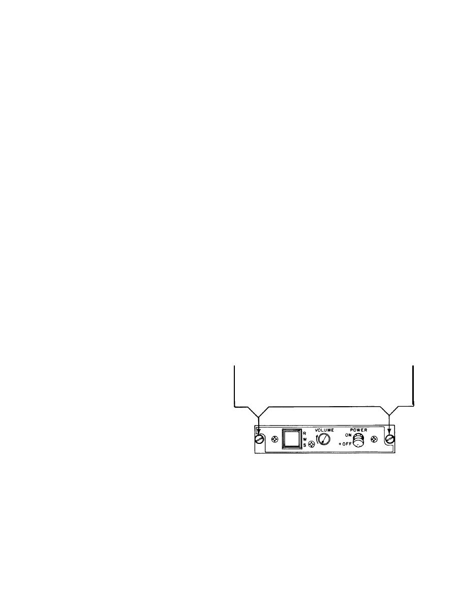
a. Loosen two captive turnlock
fasteners that secure control unit
to aircraft mounting panel.
receiver as follows:
a. Disconnect three cables from
receiver.
b.
Remove bonding strap from receiver.
c.
Remove four screws that secure
receiver to aircraft.
3-12. Receiver Replacement. Replace
the receiver in the aircraft as follows:
a.
Secure receiver to aircraft with
Carefully pull unit from mounting
b.
four screws.
panel and disconnect cables.


 Previous Page
