TM 11-5841-291-12
3-14. Control Unit Replacement. Replace
3-18. Low Pass Filter Replacement. Re-
the control unit in aircraft as follows:
place low pass filter as follows:
a.
Connect SAM receiver cable to J1,
Secure low pass filter to aircraft
a.
AI receiver cable to J2 (if used),
with two screws.
and aircraft interface cable to J3.
b.
Carefully aline center pins of mat-
Place unit into mounting panel and
b.
ing rf connectors. After alining
secure to panel with its two captive
pins, screw connectors finger
tight. Using torque wrench
turnlock fasteners.
T8438, or equivalent, tighten rf
cable connectors to between 7 and
10 inch-pounds.
antenna as follows:
3-19. Removal and Replacement of Alert
a.
Remove four screws that secure
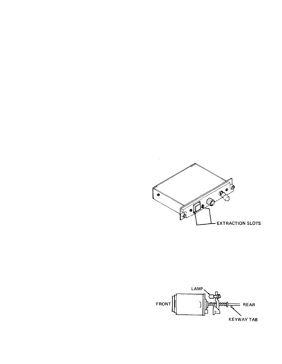
Lamps. Remove and replace lamps in
antenna to aircraft.
AI/SAM switch/indicator as follows:
b.
Carefully pull antenna away from
Remove indicator cap by inserting
a.
your fingernails in extraction
aircraft and disconnect cable.
slots at sides of indicator and
pull it straight out.
3-16. Antenna Replacement. Replace
an antenna as follows:
a.
Carefully aline center pins of mat-
ing rf connectors and screw on
cable connector finger tight. Using
torque wrench T8438, or equivalent,
tighten cable connector to between
7 and 10 inch-pounds.
b.
Secure antenna to aircraft with
four screws.
low pass filter as follows:
NOTE
a.
Check all cables connected to low
Use a flat non-metallic tool if
pass filter to see if they are labeled
your fingernails are not long
with reference designations of
enough to remove indicator
mating connectors on filter. Then,
cap.
disconnect cables from filter.
Pull out defective lamp from rear
b.
of indicator.
NOTE
If cables are not labeled, tempor-
arily mark them so you can
identify them later.
Remove two screws that secure low
b.
pass filter to aircraft.
3-11


 Previous Page
