TM 11-6625-1830-12
94D and for the portions of Radar
Set AN/APS-94D that are tested.
a. Components. The components of Interface
Test, Antenna Drive TS-2974/APS-94D are listed
in table I-l.
(fig. 6-1)
b. Dimensions of Major Components. Interface
a. The combination case is separable into two
Test, Antenna Drive TS-2974/APS-94D is con-
compartmented halves. The bottom compartment
tained in a single combination case. The case is
contains the control panel and electronics and top
19.25 inches high by 24.25 inches wide by 21
inches deep, including rubber mounting feet and
compartment provides storage for the test
guard rails. The unit, with the cables packed in
cables. All controls, indicators, and jacks neses-
the case, weighs approximately 80 pounds.
sary for the operation of the unit are located on
Figures 6-1 and 6-2 illustrate the unit and the
the front panel. The two halves of the case are
minor components, respectively.
hold together by eight draw-bolt latches that are
adjustable for tension. The combination case is
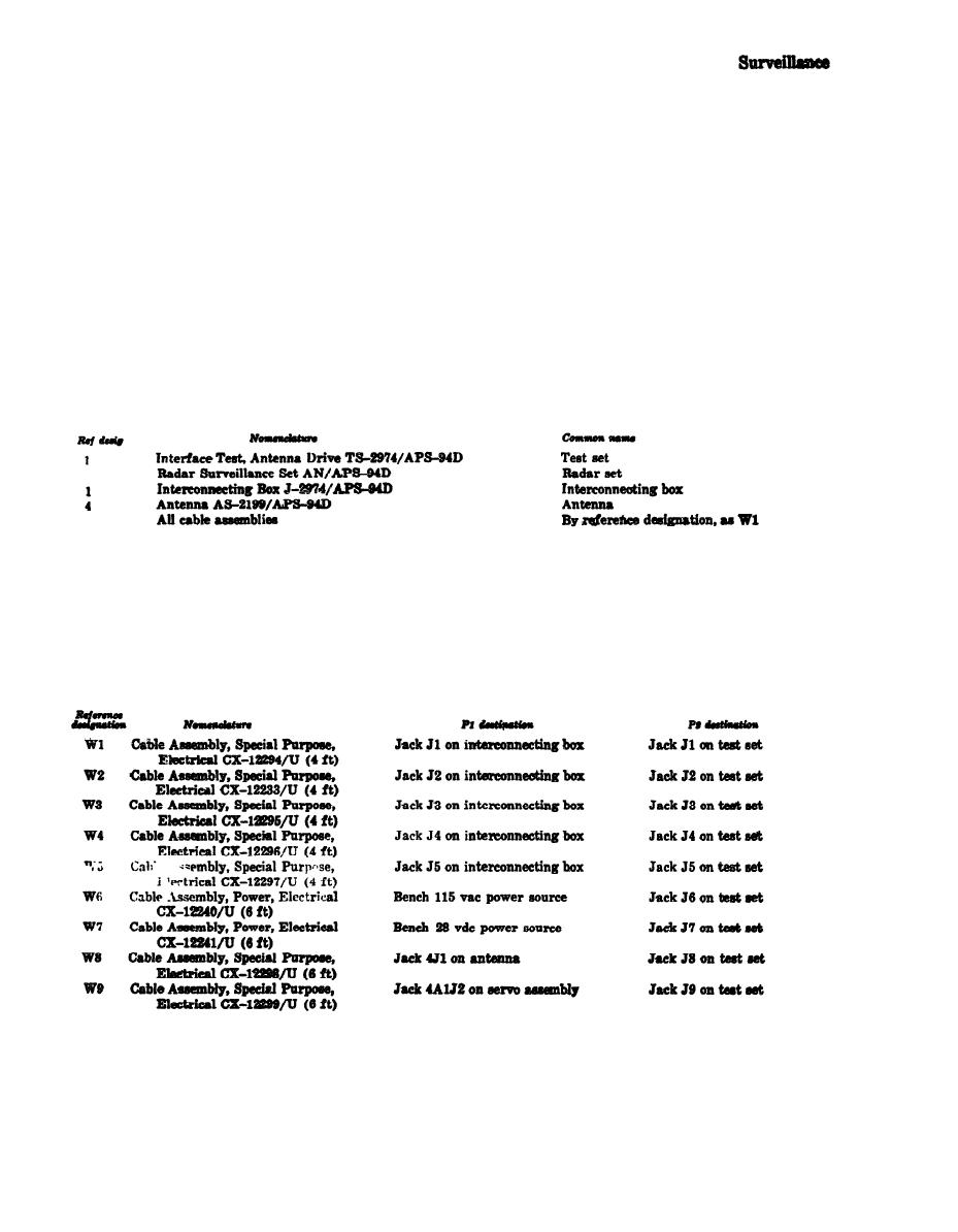
6-5. Common Name
equipped with eight rubber feet, two carrying
Table 6-1 provides common names for both
handles, and a pressure relief valve.
Interface Test, Antenna Drive TS-2974/APS-
b. The top compartment contains a hinged
(fig. 6-2)
inner door, which is secured by three push-
button fasteners. Clipped to the hinged inner
a. Minor components of the test set are shown
door is a spring scale. Also, mounted on the
in figure 6-2. The test cables are described in
door are four servo amplifier mounting posts and
table 6-2 and the spring scale is discussed in b
a stop pin.
b&W.
b. The spring scale, clipped to the top com-
AS-2199/APS-94D and the torque output of the
partment of the combination, case, is used to
servo amplifier. The scale is calibrated from 0
measure the torque required to rotate Antenna
to 20 pounds in 4-ounce divisions.


 Previous Page
